You are using an out of date browser. It may not display this or other websites correctly.
You should upgrade or use an alternative browser.
You should upgrade or use an alternative browser.
-
You can now help support WorldwideDX when you shop on Amazon at no additional cost to you! Simply follow this Shop on Amazon link first and a portion of any purchase is sent to WorldwideDX to help with site costs.
Cobra 29 LTD Classic & Chrome FM Radios are Here
- Thread starter CbRadiosPRONTO
- Start date
Anyone else notice the good adjacent channel rejection? Also I think the encoder is as good as the one on my lincoln 2.
So maybe a dual Expo signal injection 1 for transmit and 1 for receive just saying if possible would have to work so the transmit is injected when transmitting and the receive injected when just receiving controlled by a switch/relay. I'm looking at this as a split tx/rx system. I guess 1 way to stop or make hard channel mods. On the regular 29LTD the magic cap is C87 to inject the signal or L22 to inject a signal. Well good luck in trying to figure it out.When comparing the new AM/FM radio to earlier model schematics, other than the PLL daughterboard section, and FM daughterboard section, the rest match up (mostly) to the same on the schematics as, say, the 29 LTD Classic. C65 (.01uF or 103) feeding the TX buffer TR16 and most of the rest of the TX and RX, TX Switch TR21, etc... match up.
I did verify that the yellow wire going to the Ch9 switch to the Ch9 pad on the CPU board, when moved to the Ch19 pad next to the Ch9 pad, does make the radio go directly to Ch19, so that would be a good idea for the truckers radios if they wanted instant Ch19. The faceplate won't say Ch19 above this switch, but it works.
The PLL outputs 37.660 MHz on Channel 1 in RX, and 38.100 MHz on Ch40. TX frequencies are direct to 26.965 (Ch1) and 27.405 (Ch40). Both RX and TX "samples" are present at C65 (input to TX Buffer) and JP39 (14mm) which feeds R17 then FET1 (RX 1st Mixer).
Gosh, it almost seems easier do the poor man's freq mod on an older 29 and drop FM in it.
You mean, an Expo100 "A" kit?


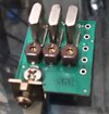
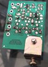
This is the smallest "A" kit you will ever find. It has 4 bands, 1 up, 2 down, plus regular. So, A= -80, B= -40, C= regular CB and D= +40. And has auto-switching. C87 is removed and is now on the board.
I used to "roll my own" FM boards on perf board, back in '84/85 or so. I need to redesign an FM board to include Noise Activated Squelch, like a 2 Meter FM only radio has.
This "A" kit will not work with the new AM/FM C29's though. But, I have a few ideas.
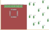
The CPU board is 40mm x 44mm (or 42mm ?? Need to remeasure again).
Replace the whole CPU board with one of our own??
Or, (I'm working the bugs out of, before submitting the Gerbers) (see earlier posts by me about HTX10 and 980SSB), my Double Mixer Universal PLL cracker design would also work, I'd have to change the filtering on the outputs to have 2 paths, so 37 MHz goes to the RX 1st Mixer, and 27 MHz goes to the TX Buffer.
NZ8N any schematics for the board. And what is the part # for that metal bracket or where can they be bought? thanks.You mean, an Expo100 "A" kit?
View attachment 63367
View attachment 63368
This is the smallest "A" kit you will ever find. It has 4 bands, 1 up, 2 down, plus regular. So, A= -80, B= -40, C= regular CB and D= +40. And has auto-switching. C87 is removed and is now on the board.
I used to "roll my own" FM boards on perf board, back in '84/85 or so. I need to redesign an FM board to include Noise Activated Squelch, like a 2 Meter FM only radio has.
This "A" kit will not work with the new AM/FM C29's though. But, I have a few ideas.
The CPU board is 40mm x 44mm (or 42mm ?? Need to remeasure again).
Replace the whole CPU board with one of our own??
Or, (I'm working the bugs out of, before submitting the Gerbers) (see earlier posts by me about HTX10 and 980SSB), my Double Mixer Universal PLL cracker design would also work, I'd have to change the filtering on the outputs to have 2 paths, so 37 MHz goes to the RX 1st Mixer, and 27 MHz goes to the TX Buffer.
we are talking about the new FM 29s not the oldGosh, it almost seems easier do the poor man's freq mod on an older 29 and drop FM in it.
Right, we are talking about the new FM 29. I'm really interested in learning more about the offset mixing that NZ8N has described.
I'm not sure why there are pictures of crystals. Isn't that for the older 29?
I'm not sure why there are pictures of crystals. Isn't that for the older 29?
Yes for the older 29s but I guess to reference the older 29s to the newer FM 29s.
Will be interesting if the newer FM 29 can be modded for channels, time will tell
Will be interesting if the newer FM 29 can be modded for channels, time will tell
Credit to NZ8N for showing us the boards he has worked so long to develop, along with other projects.
73
Jeff
73
Jeff
Well I think the si5351b might be a contender. I'm having trouble understanding the offset thing. Does that mean that the original signal is mixed with a 440khz signal to create "bands"?
Will it provide access to the "A" channels and a freq counter? I know that the crystal mod doesn't provide either without further mods.
Yes, thanks to NZ8N for posting those pics with a nice description of the operation.
I would be very interested in purchasing this offset mod.
Will it provide access to the "A" channels and a freq counter? I know that the crystal mod doesn't provide either without further mods.
Yes, thanks to NZ8N for posting those pics with a nice description of the operation.
I would be very interested in purchasing this offset mod.
The previous pic was of the smallest "A" kit you will ever see. This is for the older gen 29's, with either a uPD2816 or the Cobra29 Chinese clone that fits the 29's. This does the 15.36 over-ride.
The new AM/FM radios, along with the latest gen of the 29LX, has the new CPU serial data driven Beken BK4802P frequency generator, which has an internal Fractal-N PLL and no way to offset the signals (37/27) as now designed. It is an internal connection inside the chip, and can not be broken inside of this chip. So, one of my ideas involved adding a data go between (Arduino), that intercepts the PLL data, does fancy math, then sends it to the Beken chip.
But, rather than a go-between, why not just build a replacement CPU board instead? Either to output our data to the Beken chip (which has the FM injection input for TX), or to an Si5351, but we'd need to figure out a way to FM the signal from the Si5351 (only in FM TX, though). If using the Si5351, could put that on the back side of the new replacement CPU board.

I have mapped out most of the lines from main board to the CPU board, some I hadn't traced yet, though.
J4 of the main board, ribbon cable pin-out that I have traced so far
Pin
1 - W20 (Grn) - Wiper of Delta Tune
2 - CLK - PLL Board
3 - Data - PLL Board
4 - TX-RX - PLL Board
5 - JP47 - AM-FM on FM Board
6 - W26 (Blu) - R19 by transformer back right corner ???
7 - RSW (Org) - AM Det area (I think it "kills" the AM 2nd IF in FM mode)
8 - R44 (104) to Gnd - R42 to RX +8v ?? Voltage divider to know if in RX ??
9 - JP22 - TR22 Brt-Dim (for LED drivers)
10 -
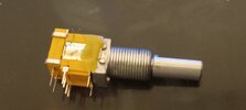
The ribbon cable from the CPU board to main (J4) are stiff, when I tried to reposition it to see underneath, I broke the CH selector, I had to further remove the CPU and LED display boards (hot glued to the faceplate). I bent the shaft of the CH selector a little, desoldered the switch from the CPU board, straightened it out before reassembling the switch, and pinching the grabber tabs to hold the switch together.

The new AM/FM radios, along with the latest gen of the 29LX, has the new CPU serial data driven Beken BK4802P frequency generator, which has an internal Fractal-N PLL and no way to offset the signals (37/27) as now designed. It is an internal connection inside the chip, and can not be broken inside of this chip. So, one of my ideas involved adding a data go between (Arduino), that intercepts the PLL data, does fancy math, then sends it to the Beken chip.
But, rather than a go-between, why not just build a replacement CPU board instead? Either to output our data to the Beken chip (which has the FM injection input for TX), or to an Si5351, but we'd need to figure out a way to FM the signal from the Si5351 (only in FM TX, though). If using the Si5351, could put that on the back side of the new replacement CPU board.

I have mapped out most of the lines from main board to the CPU board, some I hadn't traced yet, though.
J4 of the main board, ribbon cable pin-out that I have traced so far
Pin
1 - W20 (Grn) - Wiper of Delta Tune
2 - CLK - PLL Board
3 - Data - PLL Board
4 - TX-RX - PLL Board
5 - JP47 - AM-FM on FM Board
6 - W26 (Blu) - R19 by transformer back right corner ???
7 - RSW (Org) - AM Det area (I think it "kills" the AM 2nd IF in FM mode)
8 - R44 (104) to Gnd - R42 to RX +8v ?? Voltage divider to know if in RX ??
9 - JP22 - TR22 Brt-Dim (for LED drivers)
10 -
The ribbon cable from the CPU board to main (J4) are stiff, when I tried to reposition it to see underneath, I broke the CH selector, I had to further remove the CPU and LED display boards (hot glued to the faceplate). I bent the shaft of the CH selector a little, desoldered the switch from the CPU board, straightened it out before reassembling the switch, and pinching the grabber tabs to hold the switch together.

Attachments
Last edited:
I didn't know it was possible, but apparently you can FM modulate the Si5351:

 la3pna.wordpress.com
What I don't know is when you do what the article suggests if the FM modulation only shows up on one output, or all active outputs?

Si5351B FM modulation
The Si5351B have an interesting feature in that it can be FM modulated via the VCXO pin. After some discussions with Jason NT7S about the VCXO feature in his last revisions of the Si5351 library we…
What I don't know is when you do what the article suggests if the FM modulation only shows up on one output, or all active outputs?

