• You can now help support WorldwideDX when you shop on Amazon at no additional cost to you! Simply follow this Shop on Amazon link first and a portion of any purchase is sent to WorldwideDX to help with site costs.
  • Click here to find out how to win free radios from Retevis!

Cobra 29 LX Max no xmit...

Thanks Brandon, you got darn good eyesight. I checked in that area time and time again, never even noticed that. I'll swap that out and get back with you.

Would this also keep the base and emitter of the driver at 0v in both receive and transmit?
 
Would this also keep the base and emitter of the driver at 0v in both receive and transmit?
The emitter will almost always be at ground in any class C power stage. As for the base of the driver being at 0v (or the final for that matter) in this particular radio, there is no DC bias present. The only time these transistors turn on is when the positive going part of the predriver's RF signal is high enough to forward bias the drivers Vbe junction. This is about 35% of the total RF cycle. To a simple DMM, those "DC pulses" are probably too short and too fast to see.
 
  • Like
Reactions: Hawkeye351
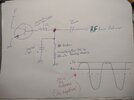
I say that you wouldn't see DC at the base with a basic DMM, but that's not entirely true. You might read a slightly negative value. The b-e junction rectifies the RF and you will get a fraction of a volt negative at the base under normal operation. If your DMM is good enough to see DC in the presence of RF, the base voltage will be slightly negative with respect to ground when in transmit.

Edit: Here's where the negative DC comes from in picture form
DC.jpg

The reason for creating the negative base voltage is so that with a 2v peak signal, instead of turning on at 0.7v, it waits until the + going signal is 0.7v PLUS that negative bias voltage. This means the device is on for a shorter part of the RF cycle. Its mostly an efficiency thing.

The value of the cap needs to be small enough to not shunt all of the RF but enough to store some DC and affect the bias point. The resistor can then be chosen for a DC bias that is negative enough that combined with the Vbe drop, results in the transistor conducting only 35% of the time.
 
Last edited:
  • Like
Reactions: Hawkeye351
Removed R56 from circuit. The bead wasn't cracked, it was that glue on it that made it look like it was cracked. Replaced it with another one anyway, along with the resistor (resistor tested at proper ohms), still no output, same results.

TR16:
Voltage chart calls for GDS from TR16, but doing a search on 2SC3800 shows a BJT with BEC. The following is with the front of TR16 facing me, parts side up, front of radio facing me. I'm just gonna mark them as Left, center and right.

Receive
Left lead (nearest chassis) = 0.00v
Center lead = 0.01v
Right lead = 0.72v

Transmit
Left lead (nearest chassis) = 0.38v
Center lead = 8.08v
Right lead = 0.54v
 
Left is emitter, center is collector, right is base.

Edit: I am not sure, it looks like the base voltage might be is a bit low in TX. Yea it's definitely low compared to the emitter. Should be .6 above the emitter when on.
 
Last edited:
  • Like
Reactions: Hawkeye351
What voltage do you get on the left side of R62 in TX?

Edit: The PLL lock detect pin (IC1 pin 15) should be high.
 
Last edited:
  • Like
Reactions: Hawkeye351
R62 left side lead voltage in receive is 2.72v.

R62 left side lead voltage in transmit is 2.07v.

If I'm counting the pins right, IC1 (PLL) pin 15 voltage is 2.40v.

Radio receives great on all channels.
 
Last edited:
This is where one of the wiser techs may need to chime in lol because I just calculated the current through the base and the current through the emitter and got a gain of 70 and now I am thinking this amplifier is also class C and biased for roughly 35% of the conduction time. That's supposed to be class C, right???

That may be the right voltage there, and at this point, I really don't know. It might be time to take out that scope and look for the RF. Would be much quicker.

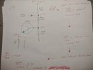
IMG_20240213_194729499.jpg
 
Last edited:
  • Like
Reactions: Hawkeye351
Determined to know (for sure if it is class C (because that PLL pin voltage you gave me was throwing me off), I just popped the covers of my 25 (very similar predriver) and yes, in TX it is class C. Those transistor voltages in TX look correct. I do have 7v on my PLL pin though. Back row, 4th from right. Check again if you want to.
 
Last edited:
  • Like
Reactions: Hawkeye351
I think we need to back up. With your first post suggesting you have full indication and good modulation on the monitor radio, and being everything to this point seems to have checked out, I think we need to back up and look closer to the output jack. Maybe the coax connector is worn, maybe a filter component is bad, something tells me its not going to be found further back than this.
 
  • Like
Reactions: Hawkeye351
We can find out really fast if a filter cap shorted. Just ohm the coax jack. If no caps failed, all you will see is the 1k static discharge resistor.
 
  • Like
Reactions: Hawkeye351
When i encounter issues like this i get the scope out and start probing from the TX mixer output to the antenna jack.

Sometimes one of the mixer inputs is missing, but most of the time its one of three things, a bad transistor, a bad tuning coil, or tuning issues.

in cobra 29LTDs especially, there are tuning coils in the TX chain that will sink your power down to nothing and make you think you have a problem that isn't really there. L17 can cause this if misaligned.

just as a side note since this comes up alot when talking about the TX chain in a 29LTD, don't be fooled by the schematic when it comes to L16.
it shows as an adjustable coil but you'll find no slug in it.
This coil has nothing to do with tuning and is just an RF filter going to the collector of the driver.
LC
 
Got it guys. Transmit back up to par.

Culprit?
R123 was open, showing no ohms in circuit. Yanked it out and checked it, still no ohms. Replaced with new 1 ohm 1/4w 1% and bingo, output is back.

Thank you guys for helping me out.
 
Got it guys. Transmit back up to par.

Culprit?
R123 was open, showing no ohms in circuit. Yanked it out and checked it, still no ohms. Replaced with new 1 ohm 1/4w 1% and bingo, output is back.

Thank you guys for helping me out.
for clarity... when you say 'no ohms'........ was it zero ohms (shorted)?
or was it infinite/OL ohms (open) ????
 
sneaking in a 'post of thanks'....

@loosecannon @brandon7861

I have always had a bit of a weakness in the area of 'driver and final biasing'.
I was fairly sure about how bias worked on SSB rigs...being that it is generally Class B...

But Class C biasing on AM rigs... was a little bit of a 'third water mystery'.

Input from the two of you have REALLY been an 'eye opener'.
It's like.... just watching the two of you 'lend a hand' here...
the input you were giving.... just went MILES in making sense out of it to me.

And for that.... I thank you both!!!!!!
Best regards,
Bob
 
  • Like
Reactions: loosecannon

dxChat
Help Users
  • No one is chatting at the moment.
  • @ BJ radionut:
    EVAN/Crawdad :love: ...runna pile-up on 6m SSB(y) W4AXW in the air
    +1
  • @ Crawdad:
    One of the few times my tiny station gets heard on 6m!:D
  • @ Galanary:
    anyone out here familiar with the Icom IC-7300 mods
  • @ Crawdad:
    7300 very nice radio, what's to hack?
  • @ kopcicle:
    The mobile version of this site just pisses me off