• You can now help support WorldwideDX when you shop on Amazon at no additional cost to you! Simply follow this Shop on Amazon link first and a portion of any purchase is sent to WorldwideDX to help with site costs.
  • The Feb 2025 Radioddity Giveaway Results are In! Click Here to see who won!

Cobra 29LTD/GTL 10 KC mod????????

dss56

Well-Known Member
Sep 27, 2010
397
114
53
56
Is there a 10KC mod channel jump to get the missed A channels?
I have searched the web and found a few ideas but do not work..
It the upd2816 pll thats in these radios and many other models.

Would anyone have any info for the Cobra 29LTD and GTL 40 ch radios?
 

This is dictated by the type of PLL chip connected to the channel selector. That radio has a chip that just won't do this trick. The 2816 chip is a later design that's intended to lock you out of adding frequencies the simple way. Also locks you out of going up one channel.

73
 
Hi Nomadradio.

I tried the pin 10 where you cut the 5.120 signal to L19 and injected my own oscillator. I bought some 5.120 xtals from Ali Express and well I used one of my Expo S kit with the 5.120 xtal and it would generate the 5.120 signal but no adjustment in the trim cap to off set to move the channels down 10 kc.
I think the 5.120 xtals are not cut so that there is any adjustment.

Is there any better way to build a 5.120 oscillator to adjust to inject into L19 to get the 10KC jump?
I think if I could build an adjustable oscillator it might work.

Im looking for a fixed 10kc jump no slide.

Here is a post on using the 5.120 oscillator.


Quote from Kopsicle>I'm guessing you don't completely understand the problem.
If you shift the 5.12 x 3 (15.360) signal of course what is presented to the filter will move . 5.116666667×3=15.350000001, 15.350000001+.91+10.695=26.955000001, then the filter "sees" is 15.350000001-10.695=4.655000001.
If you pull on the 10.240 reference it actually works a bit better because the 5.12 is derived from the 10.240 then multiplied by 3 to get 15.360 , the difference is still an issue, 10.2333333 / 2=5.11665 ×3 =15.34995 =5.11665.

thanks
 
I think I am picking up what kopsicle was talking about, and I think I understand what you are asking.

The 10.24MHz crystal does two things, it acts as reference for the locked down PLL, and it also goes to the VCO mixer, which directly synthesizes the output.
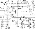
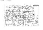
Screenshot from 2025-04-03 09-48-54.png
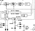
The PLL info suggests modifying the mixer crystal is about the only way to move it, and the radios block diagram suggests it is feasible.
Screenshot from 2025-04-03 09-48-18.png
But the issue here is the fact that the 10.24 is serving as both the PLL reference and the VCO mixer input. The problem them becomes separating them so the 10.24 into the VCO mixer can be manipulated without affecting the PLL reference (and thus the channel step).

The schematic I am looking at suggests 10.24 is being used directly, not 10.24/2*3. I may be wrong, shoulda been in bed hours ago, but I think what you need to do is to yank out C127 and inject your own 10.24 + 10kc into that transformer.
 
Brandon7861.

I have my oscillator board with the 5.120 xtal as I said does not trim much.
So i have it injecting it into L19 with it disconnected from pin 10 on pll. Im getting about a 6kc in moving towards the full 10 kc and if i flip the toggle on my board it will close pin 10 back and back to regular channels.
This seems to be a good way to do it so if a Expo 100 A kit is installed you will also get the missed channels that fall in to the missed A channel slots.

Just need to get an 5.120 oscillator that will adjust a bit more and all set.
I did try what I have now and it will transmit on the half channel very well.


I will also try your suggestion.

thanks
 
im using a Expo 100 S kit oscillator with the 5.120 xtal in it. I think the xtals I got from AliExpress are just not the correct spec xtal as it will not trim much at all.
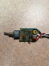
Here is picture of the expo S Kits i use for single xtal useIMG_3160.jpg
 
I see where I went wrong. I was thinking IC3 was the target of the new signal in my earlier post, I failed to realize that would only change TX. So, by attacking it at the tripler, the VCO output changes and that works for both TX and RX. I think I am getting it now.

Next bit of confusion I need cleared up. L19 is the VCO adjust. L22 is the tripler coil. You said you are injecting into L19. Did you mean L22?

On to the oscillator. Is there any schematic available? Which direction do you need it to go further?
 
As in another post it says to cut trace on pin 10 of pll that generates the 5.120 frequency to L19 and it gets trippled there to 15.360. So post says to inject your own 5.120 and trim it to get the half channels.
Like I said im half way there getting the half channels.
I just cant trim the xtal 5.120 i bought on AliExpress any more so I ordered some 5.000 mhz xtals and will try them.

Im just having fun as I sell alot of the Expo 100 A kits and many ask for the in between channels.

I tried the 10.240 xtal and adding wires to that area makes a lot of drifting.

So waiting for some 5 mhz and will try to trim up or down a bit to feed my own signal to L19 hopefully for the 10kcup or down and then close pin back for regular 40. This will leave room to add an Expo 100A kit and get the missed channels in the 40 above or below.
 
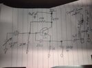
Found some pictures HandyAndy posted of a similar expo and I think I got the schematic figured out.
IMG_20250403_204325945.jpg
If the cap I labeled C2 on your board is also 22pF, it may be worth increasing to 47pF and trying again. That is the cap closest to the center of the pcb

22pF is ideal for fets, while 47pF is common for BJT versions. This cap has a significant impact on oscillation frequency. The other cap and emitter resistor are book values for 5MHz, so leave them.

As for the L19 thing, could you link me the schematic for your radio? The schematic for the 29LTD from CBTricks shows L22 connected to pin 10. Obviously, you are on the right can if it connected to pin 10, I just want to be sure we are looking at the same schematic.

5.000MHz crystals will not work. You would have to pull them way further than any HF crystal can be pulled.
 
Last edited:
The schematic you posted is the same as the picture of my Expo S kit single xtal for single band mods the post as i read says L19 could be L22 Ill see if I can post the radio schematic. The 29ltd gtl lx and NW and Weather are all the same. And now that I looked at the schematic it is L22 and not L19. The post i guess is wrong.
So the pll generates the 5.120 signal to L22 and I can do my own from the oscillator board.

Pin 10 is also where the Galaxy Expo N kit get hooked up to to get ch 42-104

I will try to change the 22pf the 47pf and see what happens.

thanks
 

Attachments

  • Like
Reactions: brandon7861
I will try to change the 22pf the 47pf and see what happens.
It will either shift it in the right direction or the wrong direction. Since I do not know which way you need to move the frequency (please tell me), this is a shot in the dark.

I removed my comment regarding direction each cap shifts it because that was an in-the-moment quote from the colpitts chapter I had open on my screen, and on my way home from work, I realized it contradicts what I have said here before and what I have read in other papers. To sort it out, I am going to build a colpitts with the same values you have and see what it does to the closest crystal I have, 6MHz. Sanity check, engage! lol
 
Last edited:
I did try the 47pf and no change I know its the xtal as there is no adjustment.
I use this kit all the time for single low channels for the cobra 29 sell them 10 kits at a time and when I put in a 14.910 xtal they trim great because I had the xtals cut that way. Dont know the specs on the 5.120 nothing on AliExpress.

So the kit as it stands now for frequency is, say channel 40 is now 27.4113 and all the A channels are 3-3A 7-7A 11-11A 15-15A 19-19A so for ch 19 is 27.1913.
So its beyond the half channel tracking up not down. Well Ill give the 5.00 xtals a shot and see what happens. About a week and will have them.

I think the xtal like i said will be trippled so the 5.120 will be the 15.360 into the L22.
Only have to be trimmed a little to generate the correct freq for the full 10kc channel jump.
 
Thanks Brandon7861

Will be interesting to see what you come up with.
Im going to take the kit out of the radio and hook up to my xtal reader and see what frequency its doing. Mose likely pretty close to the 5.120.

When I sell all my kits I pre adjust them on my reader as close to the frequency I can get. Like the Expo A kits 15.810 and 14.910 I can get those trimmed dead nuts and can adjust up or down, but this 5.120mhz xtal not much at all.

Im thinking if I get this to work it should on other pll chips that the pll you cant get the a channels. Just need the pin that produces a frequency to the trippler circuit and reproduce it with some adjustment to zero in on the A channels and missed channels with added Expo kits.

thanks dss56
 
I just finished up making my copy of the oscillator (with a 6.1704MHz crystal, its what I had) to see what affect my suggestion should have had.
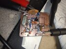
IMG_20250404_055529008.jpg
Instead of a trimmer, I used a 10pF and a 30pF in parallel. Lifting the leg of the 30pF gives me the ability to go from 40pF to 10pF, which is the extremes of your trimmer. Also, from the emitter to the base, I have two 22pF caps. Lifting the leg of one allows me to go to/from 22pF to 44pF for C2.


Results:
*counter not warmed up and no crystal is the same, just seeing the direction and ballpark amount of change*

Trimmer 10pF, C2 22pF = 6.174354MHz
Trimmer 40pF, C2 22pF = 6.172502MHz
Trimmer 10pF, C2 44pF = 6.174215MHz
Trimmer 40pF, C2 44pF = 6.172262MHz

Doubling C2 lowered the freq 139Hz (22ppm) with the trimmer at minimum, and lowered it 240Hz (39ppm) with the trimmer maxed. The effect of increasing the trimmer is a decrease in frequency about 2.2kHz (356ppm).

Edit: I need to go to bed now, my brain is scrambled when I stay up this long. I see I was looking at a JFET circuit, not a more loaded down BJT oscillator. Once again, I made myself look like a total ass. I was thinking, OK, if 10% gets 30ppm, 100% will get about 300ppm. Being you said you got it to move 6kc (about 2/3 of 10kc), I figured, ok, about 3kc/3, or 1kc to go. 300ppm on 5.12MHz is 1536Hz, thought we had it in the bag. My apologies, I owe you a beer! I didn't realize I was looking at a JFET circuit with this particular chart.
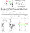
screenshot.png
 
Last edited:
  • Like
Reactions: Shadetree Mechanic


Write your reply...
dxChat
Help Users
  • No one is chatting at the moment.
  • @ Geoexplorer69:
    Coax question. I just put up a new Sirio monsoon base antenna with 100’ of rg8u coax testing with myMFJ antenna analyzer shows 1.4 swr at 26.965mhz and a 1.1 at 27.405 mhz . When I checked the ohms it’s steady a 30 ohms across the entire bandwidth.
  • @ Geoexplorer69:
    Is 30 ohms worth worrying about in a 100’ run of rg8u ?


      You do not have the permission to use the chat.