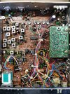
Have an old Connex 3300 on my bench needing attention. Has several clipped components and possibly some mods, but I can't seem to find any schematics or service manuals for this model. Anything I can find is for the newer 3300HP models. Anyone have anything for the 3300 non-HP?
You are using an out of date browser. It may not display this or other websites correctly.
You should upgrade or use an alternative browser.
You should upgrade or use an alternative browser.
-
You can now help support WorldwideDX when you shop on Amazon at no additional cost to you! Simply follow this Shop on Amazon link first and a portion of any purchase is sent to WorldwideDX to help with site costs.
-
A Winner has been selected for the 2025 Radioddity Cyber Monday giveaway! Click Here to see who won!
Connex 3300 schematics and service manual?
- Thread starter JDE
- Start date
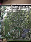
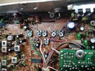
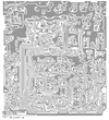
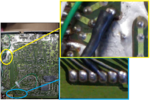
Not sure. Here are pics of both sides of the PCB, along with a zoomed in shot showing some of the carnage.
So far I've identified L33 falling apart, R240/R249/C189 clipped or removed, already replaced the DC filter cap and addressed a bunch of broken/bad solder joints on the solder side. I suspect other missing/clipped components and possibly some hackjob fixes/mods. She does tx, but doesn't sound too great. Doesn't rx at all, but audio circuit is fine. I'm still a beginner so I'm just using eyes, ears, and a dmm at the moment.
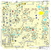
Edit: Looks like the Galaxy DX33HML might be a winner, looks identical so far and the various free cbtricks mirror sites have a wealth of info on the 33HML. Nice!
Attachments
This one looks like a flood victim, the rear panel got soaked with water, see some green from the copper corroding away.
The radio is still salvageable - but whatever hammered the back end of that final and driver - let alone R236 and Diode combo - you certainly have picked a winner.
Start with the cap - by R236 and Rear Panel power supply and also gently start to rebuild the board - it's not bad, just rear panel and areas of water entry are the problems - you don't have mold - yet.
That green stuff appears to have been from a previous cap that was in that one spot the outline is different - so when it erupted - the green is the sulfite possibly from the copper sulfate or the electrolyte steaming out of it.
Some simple alcohol - could help but if properly used, some MEK (Methyl-Ethyl-Ketone) to get the stiffer stuff would help. The Green should flake off and some simple Isopropyl to help with the trimmer's rotation should be all that is needed to get that stuff off.
Note the rear panel support "Ears" or the riveted lugs used to hold the rear panel in place as RF ground return - you will have to drill out the rivet and replace with bolts and nuts to restore the rear panel RF backplane - else you may have issues with the Rf being produced back there. So, if initial tries and you still have problems - the next step is rebuilding that back panel to make the RF flow in the correct directions to work right.
Several spots by the AM regulator - looks like they did "Frankenstein" style surgery by removing the back cover and subbing in parts and values until they achieved an effect or made it work like they wanted to. Then kept parts in and then the radio wound up on a market and in your hands.
This is where an air station would help reflow the solder to take up the flux still left and bring the shiny solder to rewet and doing so gets the dirt out and float it to the top for easier cleaning.
There is a mod of some type done to the 4558 chip on that board so I'll have to leave these with you to help you sort out the work...
Not sure of the status of the Echo board, it is an early 50B type.
But aside from the age and the environment it was left in - it should be workable as a recovery - but gently first...see if you can get a heartbeat then work on the amputations and organ reattachments.
You have some work to do - and to be honest - I've seen worse arrive to my desk and have had to restore bigger messes - but that is an NDA for later...
Attachments
My plan was to get it cleaned out, replace the cliped/removed/modified components, then start doing the easier alignment steps that only require a dmm to see if I can restore basic functionality. As it sits it does TX on AM, haven't tested on SSB, all the switches/knobs seem to work, meter is dead, and it has no ears. I don't have lab gear yet...'scope, signal gen, sinad meter, etc...since I'm still trying to learn the circuits and troubleshooting/physical repair stuff first.
IF you currently have TX just no receive - you have half the battle won.
We'll be here if you need some guidance - just be patient with it...
We'll be here if you need some guidance - just be patient with it...
Fixed a series of bad solder joints on the foil side.
Removed R240 and C189 from the foil side and put them back on the component side.
Cleaned up/reflowed all the RF chassis grounds. Haven't drilled out those lugs to replace with better hardware yet, but there is at least continuity at each solder joint tested against the chassis.
Replaced meter, original was frozen on the far left.
Removed, re-assembled, and reinstalled L33. Whatever job this slug-adjusted coil does, it likely isn't going to be doing it well. I'd like to get it replaced but not sure where to get a replacement.
Removed D93, replaced with larger diode across the rear power socket terminals.
Already replaced C195, it's smaller than the last one but same specs.
Haven't tested TX/RX on FM or SSB yet. Also haven't replaced the clipped R249.
Symptoms/issues after the above fixes;
-Does TX but with static, not very loud/clear, listening on a nearby monitoring radio. Hi/Lo power doesn't seem to make much of a difference coming out of the monitoring radio. Both radios are connected to dummy loads and about 6ft apart.
-RF power switch set to low, dead keys around 1-2w, swings up to 12-13w. Set to high, dead keys around 2-3w, only swings up to 10-11w. I'll assume this is an alignment issue.
-It actually does RX, but it's one channel off/low. TX from monitoring radio on CH7 is heard on this radio on CH6, and quality is low/medium.
-There are several lifted tracers on the foil side of the PCB, they would be in the top-left corner if looking at the photo I attached earlier. They don't appear to be broken yet, but I will probably clip them and replace with jumpers to avoid issues.
-New meter doesn't move on RX. Does move on key and shows swing.
-You mentioned a mod being done on 4558, is that the NJM4558 chip marked as IC4? If so, from what I can see a previous person soldered the legs together of R174 and C128 because the common trace between those two pads was missing, but all the solder joints on IC4 look factory.
When you hear crackling - then I worry.
The issue of IC4 (4558) begins to mount.
Check the parts - these Galaxy radios were often prone to cracked (as in open) resistors - the crackling sounds are more than likely from the Receiver side - so there may be open lines or failed caps in the RX section.
More than likely - power feeder filter caps.
No crackling, apart from when I mess with the channel selector knob, probably dirty contacts in that.
Haven't found much information in the way of why this thing transmits on the right frequency/channel, but receives on a channel lower than what the TXing radio is transmitting on.
Haven't found much information in the way of why this thing transmits on the right frequency/channel, but receives on a channel lower than what the TXing radio is transmitting on.
Did you want talkback?
No?
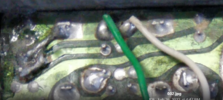
Then remove that black wire...foil side to Audio Chip
View attachment 57687
Thanks for that, was wondering about this after realizing the radio had talkback last night. I need to find more info about that particular modification so I can see how it works, I think it is enabled/disabled by the echo switch?
As for the "recieving on a lower channel, transmitting on the right channel" issue I went through all the pots and switches with CRC QD Cleaner, twice. I even had the front bezel and knobs off for better cleaning access, when I was replacing the meter. All the switches and knobs seem to work. No 10khz switch like on my General Lee. This problem has existed since I received the radio, so nothing I've done so far caused or affected it.
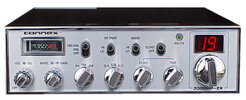
Attached is what the front panel of this old 3300 looks like, disregard the 3300HP-ZX, it's just a photo I found on google that matches what my 3300 looks like.
I can get a photo of the component-side of the echo board later today, and maybe a close up of the backside of the front panel to see all the pots and their wiring.

