• You can now help support WorldwideDX when you shop on Amazon at no additional cost to you! Simply follow this Shop on Amazon link first and a portion of any purchase is sent to WorldwideDX to help with site costs.
  • The Retevis Holidays giveaway winner has been selected! Check Here to see who won!

Connex 3300 schematics and service manual?

I've been slowly working my way around the foil side trying to get the solder blobs and balls fixed, and making sure there are no shorts anywhere. Whoever worked on this thing didn't quite have their soldering skills down.

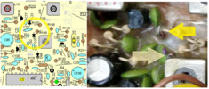
In that second photo, left side, that is the top-left corner of my foil side photo from earlier. Note the clear substance all over that corner. Someone installed two jumpers there, and I can see the traces to that area lifting from the PCB. Not sure what happened there, but when they were done "repairing" it, they dumped some sort of adhesive/glue all over it. Thanks for that one, previous repair guy.
 
Then run a voltage check - locate J105...

The F E D silkscreen and there is a 10kHz line right there by G for board ground (large foil versus 8V runner foil to the front panel side) - see if it changes...

Sorry, when I talk Clarifier Fine coarse - just get used to looking for a voltage on this header...it's part of the bandswitch and the 10kC jump

Which may mean you have a diode array or 4008 Adder chip going bad.
 
  • Like
Reactions: JDE
1646057426512.png

There are wires to the header and pins from this head to the front panel - tells me there is a wire going up from here - so that is what sends up the red flag - wiring or switch issue?
 
  • Like
Reactions: JDE
Looks like as I post, they are working on this site at the same time - so adds a little fun / delay / interesting results as the site upgrades occur while we post back and forth - so I'm going on break for part of the day - I hope I have not given you a big headache from efforts of flurries of postings going back and forth...

Lots of stuff gets crossed in the mail...
 
  • Like
Reactions: JDE
I'll take a look at J105 header later after work and figure out what that 10khz wire runs up to. Thanks for all the info!
 
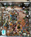
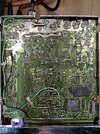
First picture is component side of the board with the echo board moved out of the way.

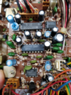
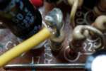
Second picture is close-up of component side of echo board.

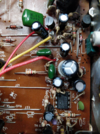
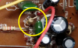
Third picture is close-up of component side of PCB under the echo board. Note the yellow wire going to resistor R210, I believe this wire goes elsewhere on the board and may be factory? On C196, not sure if that was factory goop or cap leakage so I went ahead and replaced it.

More pics/info inbound.
 

Attachments

  • 010.png
    010.png
    17 MB · Views: 21
  • 011.png
    011.png
    11.3 MB · Views: 18
  • 012.png
    012.png
    7.4 MB · Views: 16
Last edited:
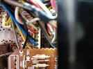
First picture is a close up of the J105 plug, green wire(10khz) is clipped flush with the plug, this is done at factory on boards destined for radios without a 10khz switch. There are 1 or 2 mods I could try to give this 3300 that functionality if I want it.

Second picture is foil side after cleaning up solder joints for the green/white wires and replacing C196. Still a lot of cleanup to do back there, holding off until my Amazon order gets here...99% iso alc, static-safe cleaning brushes, and water-based flux.

Ran some more tests tonight between this radio and my General Lee monitoring radio. Both on ch3, TX from the GL to the 3300, nothing on 3300, meter doesn't even move. Move up to ch4 or flip the +10khz switch up on the GL, 3300 receives on ch3 but with some feedback/noise. TX from the 3300 is fairly clean, surprising from the poor condition this radio was in.

I'm getting pretty close to having this back to fully functional and ready to be thrown on the shelf with the others, waiting on me to learn more so I can start aligning them.

Also, the back panel is definitely bent. The antenna connector area is pushed in. Guessing someone dropped it and it landed on that end.

Edit: The diode added to R238 and R249 being clipped is a popular mod done to this board to allow you to dead key at 1w and swing up to max, but apparently some folks prefer turning up VR14 isntead of clipping R249.

I can't seem to find any info about the green/white wires from J103 to those pads between the 3.5mm jacks.
 

Attachments

  • 007.jpg
    007.jpg
    1.1 MB · Views: 7
  • 008.jpg
    008.jpg
    3.3 MB · Views: 7
Last edited:

1646140204268.png
R210 is the "stock" version of talkback / PA - some also use a spot by this point for "Direct inject" Hi-Fi (wideband) audio. Here...

1646141437728.png
R235...​

Can't find the wire in the photo of the loom to trace back to the front panel - but I believe it goes to the board just behind and to the left of "Volume" control.

Now that you've had the radio on and corrected several areas, how is that "noise factor" you originally had - doing?
 
Last edited:
  • Like
Reactions: JDE
I can't seem to find any info about the green/white wires from J103 to those pads between the 3.5mm jacks.
1646141128873.png
Since you asked, I believe they are supposed to be the Violet and White wires from the area by J103/J102 - that head back to the EXT SP and PA jacks - more than likely they are the CB/ PA switch wires that ground that particular selected jack - (speaker return) - at least supposed to. You don't normally see these wires on the bottom - but looking at where there is a LOT of damage (overheating condition) back there at the power input - they rerouted wires to the bottom foil side.
 
  • Like
Reactions: JDE
So if R210 is factory talkback, I wonder why they ran that black wire+resistor from Pin 46 of J108 to one of the legs of IC8? I can't seem to find anything on google about this modification.

The yellow wire from R210 goes to one of the two empty pads for J9.

Makes sense on the green/white wires. I'm going to try cleaning up that corner of the PCB and maybe move the wires topside again.

TX on ch3 from the 3300 sounds mostly OK on the monitoring radio, same feedback/hum I get with any radio likely due to lights in the garage or my old radioshack power supply used for bench radios. RX on 3300, not sure if it's just me but it seems like it cleaned up a little after replacing C194 and C195, but still a bit low and scratchy likely due to every one of the caps in the 3300 being 20 years old.

3300 still seems 1 channel or 10khz low on receive. Both on ch3, I have to kick the monitoring radio +10khz on in order to tx from it and hear myself on the 3300.
 
The Talkback was switchable - screaming into your external speaker

The Black wire one looks like it was adjustable - and you heard it all the time - the black shrink wrap more than likely has a resistor of about 270K to 470K - to push down the amplified noise - er mic audio - from the echo board so they could "tweak" the controls.

The radio has a TX and RX offset - so that means - and since ruled out - any 10kC mods - so it more than likely is the VCO switch from RX to TX and back again - the cap they put in when RX is on, slows down the VCO to allow the 455kHz offset and that may be the problem you have - either the RF switch used to turn it on and off - is bad - or the cap is drifted to a value that makes it useless.

1646166355284.png
1646166313686.png
 
  • Like
Reactions: JDE
Another aspect, is to know if the TX crystal is the one HIGHER than the expected RX frequency?

Because to the system, the TX side uses that offset - but the High/Low switch that gives the radio all it's bands - can throw you for a loop - so the D33 and D123 have to be verified that they are working.

The other offset? Deals with TR30 - the TX 10.697 X4 - see if that frequency is supposed to be what it is. It is not used in the PLL side - but the RX does have a deviation pot VR5 - now it affects the Varactor, for the PLL.

So if FM-2- AM issues show up - it may be in this area - VR5 and the two Diode splitter D31 and D32. It may not affect the frequency directly - but if the cap used to "vibrate" the Varactor with audio - can fail - and load down the line that the Varactor tunes with. That fluctuation as a frequency shift, can show up on TP2.
 
  • Like
Reactions: JDE
Finally got this radio back on the bench.

I believe you're right on the green/white wires on the foil side, disconnected I have no speaker, so they likely ran these foil side due to the damage in the power area.

The receive is still poor, but both this radio and my tuned/aligned General Lee were on CH4 and TX/RX back and forth. Last time I had this radio on the bench it was receiving 1ch low, but wasn't this time. I wonder if the RX drifts when it warms up?

I've thoroughly inspected the foil side, cleaned up what I could, confirmed no shorts, no more bad solder joints. At this point I think I'm just going to be chasing and replacing old/bad components, probably a lot of bad caps on this old rig.

I think I have all the electrolytic caps in stock, but I haven't yet put in an order for disc caps. I'm going to try to identify them visually, compare against the schematic of the 14b board, then see what I can find on digikey.

According to the Bird43, on RF output low I'm dead keying 2w and swinging 4w, and on high I'm dead keying 3w and swinging 5w. I think the aftermarket peak kit I put in the Bird is lying to me so I'll check on an MFJ cross-needle to see what it says, but this could also be a result of old components or that oxidation/corrosion on some of the trim pots.

Is it possible to wire the un-used 10khz wire to the CB/PA switch, so I can have switchable +10khz?

Edit: The only frequency counter I have at the moment is a cheap chinese one w/ bnc connector from ebay that would surprise me if it were accurate at all. I need to get an RF sampler bought or made before I can use it, though.
 
  • Like
Reactions: Handy Andy

dxChat
Help Users
  • No one is chatting at the moment.