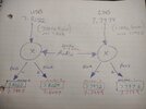
Maybe I could cheat and pick off the lower frequency PLL signal after the divider and do the math in the arduino.. The arduino nano can measure frequency up to 8MHz I believe, Not sure on the accuracy though, I have yet to try. In all my electronics experimentation, I still have never owned an LCD display for an arduino lol.Maybe use a DS3231 RTC clock module to provide a 1PPS signal to a SN74LV8154 which in turn feeds a MCP23017, so that frequency and time can be read by an Arduino or Pi zero that can then drive a display for both? Or is that just a bit too far out there?
-
You can now help support WorldwideDX when you shop on Amazon at no additional cost to you! Simply follow this Shop on Amazon link first and a portion of any purchase is sent to WorldwideDX to help with site costs.
-
The Feb 2025 Radioddity Giveaway Results are In! Click Here to see who won!
Crystal filter question
- Thread starter brandon7861
- Start date
I would do the alignment steps for carrier balance and carrier oscillators, before calling this a failure.Well, I must have either screwed up in my assumptions or this filter is a little out of whack too. The numbers in the manuals match, even the VCO frequencies, so I assume the filters started out the same, but maybe it drifted a little.
I feel like an idiot calling the alignment done before zooming in and looking closer. After seeing the harmonic problem fixed and things on the SA looking good zoomed out, I took a quick look at the waveform using the scope as I put 200 to 2.5kHz into the mic. Why I didn't use the SA, no clue. Intensity didn't drop much at all. Sounded good on the air too, great reports, even called the guy on the other end to hear for myself. All seemed GREAT.
All was not great, he could hear me on the other sideband. Not as loud, but I was in there.. Checking with the SA, I now see that 1kHz into either sideband produces the desired signal, but also the same signal in the other sideband that is 20dB down. If I put 1kHz in, say on 27.205 USB, I get the 27.206, but also 27.204 at -20dB. Works the same the other way. The rolloff in the other band begins at about 200Hz and doesnt disappear until about 1.5kHz. 20dB is less than 4 s-units difference, thats not acceptable. My washington does not do that.
I did all the alignment steps. The frequencies were spot on. With stock clarifier (changes rx only and still hot-glued in position from the alignment) I was spot on according to all my equipment and the receiving station i tested with. I know the alignment was good, he was excited his radio sounded that good.
I didn't skip the carrier balance either, I did that adjustment twice just to be sure. The first time with the oscope watching for the waveform to disappear, then later to recheck, with the SA while in SSB mode (I can still see the carrier in SA mode, but it is quite low and at its minimum).
I also did a little math on the IF frequencies which leads me to believe the filter is simply too wide,so I don't believe shifting the carrier will make any difference (edit: this statement is wrong as I later found out). What follows is with 1kHz modulation. I will explain.
The balanced modulator on USB takes 7.8015MHz and mixes it with the 1kHz to produce 7.8005MHz and 7.8025MHz. On LSB, it takes 7.7985MHz and mixes that with 1kHz to produce 7.7975MHz and 7.7995MHz. It is the closer two, the subtraction product on USB and the addition product on LSB, that goes through the filter.
However, for the offending signal to be equal in both sidebands, both of the wider two mixing products must be making it through the filter equally as well, the 7.8025MHz on USB and 7.7975MHz on LSB.This clearly indicates that shifting the carrier will not allow me to cut off the adjacent sideband interference (edit: clearly, I'm an idiot, because I could by changing them individually). It is simply the filter being too wide.
I did notice a little dent in the top, so maybe the filter got detuned. Perhaps I can desolder the can and adjust those transformers a little and bring it back into spec???
I didn't skip the carrier balance either, I did that adjustment twice just to be sure. The first time with the oscope watching for the waveform to disappear, then later to recheck, with the SA while in SSB mode (I can still see the carrier in SA mode, but it is quite low and at its minimum).
I also did a little math on the IF frequencies which leads me to believe the filter is simply too wide,
The balanced modulator on USB takes 7.8015MHz and mixes it with the 1kHz to produce 7.8005MHz and 7.8025MHz. On LSB, it takes 7.7985MHz and mixes that with 1kHz to produce 7.7975MHz and 7.7995MHz. It is the closer two, the subtraction product on USB and the addition product on LSB, that goes through the filter.
However, for the offending signal to be equal in both sidebands, both of the wider two mixing products must be making it through the filter equally as well, the 7.8025MHz on USB and 7.7975MHz on LSB.
I did notice a little dent in the top, so maybe the filter got detuned. Perhaps I can desolder the can and adjust those transformers a little and bring it back into spec???
Last edited:
Which brings me to my next crystal filter question. I know these newer radios with the 10.7MHz crystal filters are just 4 crystals stuck in a can with a couple capacitors.
But what about these older large ones? I always assumed it was the same, but with more crystals, I had absolutely no idea there was tuning transformers in them until I removed the shrink wrap yesterday. Do the larger metal can ones also have these transformers? Is there a thread on these three filter tuning cans anywhere???
But what about these older large ones? I always assumed it was the same, but with more crystals, I had absolutely no idea there was tuning transformers in them until I removed the shrink wrap yesterday. Do the larger metal can ones also have these transformers? Is there a thread on these three filter tuning cans anywhere???
Smaller crystal filters are typically made from monolythic crystals, that are two poles per unit, which makes them smaller. The larger crystal filters use larger crystals and may have more poles, making them better from higher shape factor.Which brings me to my next crystal filter question. I know these newer radios with the 10.7MHz crystal filters are just 4 crystals stuck in a can with a couple capacitors.
But what about these older large ones? I always assumed it was the same, but with more crystals, I had absolutely no idea there was tuning transformers in them until I removed the shrink wrap yesterday. Do the larger metal can ones also have these transformers? Is there a thread on these three filter tuning cans anywhere???
You mentioned having a spectrum analyzer. You should sweep the filter and see what the skirts look like. As you most likely know, crystals drift with age. The skirts of your old filter may have gone out of whack, making the filter shape useless.
What is the best way to connect it to the SA? Do I just attach some 50Ω SMA connectors to it or do I need to make a jig that has impedance matching/attenuation to it?Smaller crystal filters are typically made from monolythic crystals, that are two poles per unit, which makes them smaller. The larger crystal filters use larger crystals and may have more poles, making them better from higher shape factor.
You mentioned having a spectrum analyzer. You should sweep the filter and see what the skirts look like. As you most likely know, crystals drift with age. The skirts of your old filter may have gone out of whack, making the filter shape useless.
nothing fancy...coax to alligator clips will work. Does your SA have a tracking generator?What is the best way to connect it to the SA? Do I just attach some 50Ω SMA connectors to it or do I need to make a jig that has impedance matching/attenuation to it?
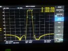
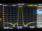
Markers 1 and 2 are where 200Hz into LSB would show up on USB and where 200Hz into USB would appear in LSB, respectively. For this filter to not allow audio into the opposite sideband, this is where the rolloff should be rolling off, but its not.
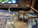
EDIT: turned peak table off to remove all those numbers in the trace and reuploaded pic


EDIT: turned peak table off to remove all those numbers in the trace and reuploaded pic
Last edited:
OK, I think I have a plan...
If I raise the USB carrier by 1kHz and lower the LSB carrier by 1kHz, assuming a 200-2500Hz audio range, the passband needs to include 7.7977MHz (marker 1) through 7.8013MHz (marker 2) and start blocking the 200Hz in the other sideband at 7.7975MHz (marker 3) and 7.8023MHz (marker 4). This looks like it would work much better.
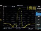
But now I need to shift the VCO the corresponding amount. I think that is possible. Turns out my original assumption of not being able to shift the carriers to correct this was likely in error. I didn't understand how these things mixed....
If I raise the USB carrier by 1kHz and lower the LSB carrier by 1kHz, assuming a 200-2500Hz audio range, the passband needs to include 7.7977MHz (marker 1) through 7.8013MHz (marker 2) and start blocking the 200Hz in the other sideband at 7.7975MHz (marker 3) and 7.8023MHz (marker 4). This looks like it would work much better.

But now I need to shift the VCO the corresponding amount. I think that is possible. Turns out my original assumption of not being able to shift the carriers to correct this was likely in error. I didn't understand how these things mixed....
I don't have the Sam's for the 148 handy, so I grabbed the closest thing I do have, which is the one for the 140 and 142 GTL (CB-219). It's got the 7.8 MHz oscillator settings as 7.8025 for USB and 7.7975 for LSB.
Both of which it looks like you've almost adjusted to anyways.
Both of which it looks like you've almost adjusted to anyways.
You are right. I was bouncing between the schematic for the TR-296GK (actual board in the 148) and the original cobra148GTL manualso much that I forgot that the crystal filter is from the stalker two, and that manual lists the frequencies you mentioned. I just pulled it out and measured it for nothing and wasted everyones time.I don't have the Sam's for the 148 handy, so I grabbed the closest thing I do have, which is the one for the 140 and 142 GTL (CB-219). It's got the 7.8 MHz oscillator settings as 7.8025 for USB and 7.7975 for LSB.
Both of which it looks like you've almost adjusted to anyways.
Stuff happens. Spectrum analyzer screenshots were cool. though.You are right. I was bouncing between the schematic for the TR-296GK (actual board in the 148) and the original cobra148GTL manualso much that I forgot that the crystal filter is from the stalker two, and that manual lists the frequencies you mentioned. I just pulled it out and measured it for nothing and wasted everyones time.
dxChat
- No one is chatting at the moment.
-
-
-
-
-
@ BJ radionut:NOTICE: The Midwest 6 Meter DX Group will be set up at Hamvention in Xenia...BOOTHS 9107-9111...COME SAY HELLO!+1

