Got a friend wanting me to install this D104 Pre-Amp plus compressor board into his D104.
The D104 has the factory amp board in it, and I had to unsolder that board to install this board in it's place. The mic is of the TUP design.
Here is the wire colors:
Green
Yellow
Red battery
Black battery
White
Black
Brown
Violet
D-104 with both PTT's.
Now I know where the red battery and black battery wires go, along with the yellow and green input wires, as well as the white output wire, and of course the black ground wire.
The 2 I'm confused about is the brown and violet.
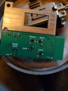
The instructions aren't very helpful. The board has the following solder pads marked as:
+ - battery positive
G - battery negative
Out - audio out
G - audio ground
S - shield
Input + - audio positive input
Input - - audio negative input
Shdn - shutdown
(This is the wire that shuts down the current draw from the board when it's not in use, keyed up).
This is how I have it wired up:
Wiring:
Green to J1 square pad
Yellow to J1 round pad
Red battery to + pad
Black battery to G pad
White to out pad
Black to S pad
Brown to G pad
Violet to SHDN pad
Do those wirings sound right?
Oh, and should the black wire (not for the battery) go to the shield pad marked S, which is for the shield or the G pad?
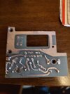
Here are pics of the original amp board I pulled, and of the new board wired in, but haven't applied power to it yet until I'm sure my wiring is right. Also a YouTube video of the exact same board by the designer testing it out.


Last edited:

