• You can now help support WorldwideDX when you shop on Amazon at no additional cost to you! Simply follow this Shop on Amazon link first and a portion of any purchase is sent to WorldwideDX to help with site costs.
  • Click here to find out how to win free radios from Retevis!

Galaxy 959 extra channels ?

dss56

Active Member
Sep 27, 2010
309
79
38
56
So I have done plenty of the 959 channel mods and they are on 4 different sections 27.965-26.665 close enough.
I know about the viagra boards-not made anymore.

So i have been reading someones post I saved and seems you can use a oscillator board to add the standard 40 up and 40 down.
use the 15.810 high and 15.360 for low.

I loaded these 2 xtals on to my oscillator board and it will work great on am dead on frequency 27.415-27.855 and 26.955-26.515.

Problem is ssb will not align. The xtals are cut for the 959.
I injected the signal to xtal 4 10.6975 on the 959 and all AM is good not the lsb or usb.

Any suggestions on a location to inject the 15.810/15.360 oscillator signal so that both am and ssb will align.

I cant align ssb with a signal injected because then when no signal the regular ssb will be off.

here is the following post I saved from a site back a few years that mentions using crystals to add extra channels.

THIS POST IS FROM SOMEONE ELSE NOT ME!
I have just check my notes on the DX959V.
I have converted a few DX959V to 10 meters with not to much trouble, the TX power will drop about 1 to 2 watts and the RX will drop to 0.35uV for 10dB on SSB, has you will not be using AM, the AM will not a problem.
Change C52 between 3pF to 5pF and C255 between 2pF to 5pF.

I have converted lots CB radios to 10 meters, this is quite a common practise in the UK.
As the 10 meter band does not suffer too much with pileup as the 11 meter band, the RX should not be any trouble.

To work out what crystals you will need, you need to do so maths.

The VCO down-mix for channel 1 is 0.91 MHz and 1.35 MHz for channel 40
The Carrier Oscillator runs at 10.695 MHz
Let us say we need 28.005 MHz for channel 1.

We know that the down-mix for channel 1 is 0.91, the carrier is 10.695, and frequency we need is 28.005.

We subtract 10.695 from 28.005, which is 17.31 now subtract 0.91 and we are left with 16.400 so the crystal we need is 16.400 MHz

To find out channel 40 we do the math in reverse, we know that channel 40 down-mix is 1.35 and carrier is 10.695, and the crystal is 16.400.

We start with 1.35 plus 10.695, which is 12.495 plus crystal 16.400, which is 28.445 MHz for channel 40.

There is a 3-band add-on board for this radio and you can find more information at CBTricks www.cbtricks.com/radios/galaxy/viagra/index.htm

Some crystals which maybe easy to find
16.260 MHz, which will give you 27.865 to 28.305
16.710 MHz, which will give you 28.315 to 28.755
17.160 MHz, which will give you 28.765 to 29.205
15.810 MHZ 27.415-27.855
15.360 MHZ 26.955-26.515

THANKS
 

The only way to make the three modes line up in the stock radio is to set the three trimmer coils, one for each mode. The crystal you use for extra channels is now in line with those three trimmer coils.

When you change crystals, those three settings are disrupted. They exist to match the particular crystal you're using. When that crystal gets changed, those three settings change.

This is why the original viagra board had two sets of those three trimmer coils. One set of three for each new band.

As a general rule, an expansion kit comes with a crystal has a trimmer cap on it for each added band. You'll need to choose which mode you want the extra-channels crystal to line up with that trimmer cap. The other two modes just won't fall into place without a separate trim adjustment for each mode.

73
 
  • Like
Reactions: brandon7861
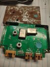
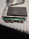
In one of my junk boxes, I remember seeing an old viagra board with a rusty shield. Not sure which one it is, A or B, or if it even works. I took it out of a radio someone butchered and later scrapped. Should I dig for it? It might still work and I have no plans to use it. No guarantee I can find it, but I'd be happy to look if it gets a second chance at life.

Edit: Found it, its the B version. I will try to power it tomorrow if I get time and see if it outputs anything. The trim caps look like they accumulated some crud, maybe it can be cleaned up.
IMG_20241105_044618360.jpg
IMG_20241105_044635329.jpg
 
Last edited:
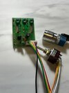
Here is the oscillator board im using its electronic switching. and works well on most radios but the 959 is a bit of a challenge.
Again I can do all 40 above and 40 below for AM but the ssb sides will not align so the middle of the rotary or the 3 way toggle is regular channels and will work great on am and ssb. the minute I inject the new freq AM fine but ssb a big no. Maybe im injecting the newer signal not in the correct place. Im injecting it into 1 side of xtal 4 for both 40 up and 40 down. Any other places to inject the newer signal?

thanks
 

Attachments

  • new a kit 1.jpg
    new a kit 1.jpg
    47.5 KB · Views: 5
Not going to work. Please re-read nomads reply.

You see how the stock oscillator in the radio has three coils that trim a single crystal for AM LBS and USB? When you add an oscillator that is supposed to serve the same function at two other distant frequencies, they too need provisions for pulling each of them into their respective modes. Your oscillator board is not set up that way.

Your oscillator board has three trimmers, so I suspect it was meant to be used for all three modes in the same channel group, with one crystal doing AM plus one of the sidebands and the other crystal doing the other sideband. You seem to be trying to use it for two channel groups leaving you no provision for mode shifting.

This is why the Viagra-A had coils to pull for SSB similar to the radios stock oscillator, and the VIagra-B went with the PLL method of doing the same without the coils. You need 6 new frequencies, but your oscillator board appears to be good for 3. Two right next to each other sharing a crystal and a third wherever the other crystal is. That is not going to work no matter where you inject it.
 
His oscillator has 1 trimmer cap per crystal, like an Expo100 A kit.

The Expo 100 "N" kit is basically an "A" with varactors added to the crystals. It does not compensate for mode selection, you would have to open your Clarifier and shift either 2.5 Kc up or down to get back to center slot.

A Galaxy Viagra board works better, The Viagra A board has individual adjustment coils on each crystal for the 3 modes, AM/USB/LSB.
The Viagra B board has an MC145106DM surface mount PLL on it, and has it set up to step in 2.5 Kc steps on the lower pins of the programmable divider for mode selection, and uses diodes to add to the 4008 adder chips for band selection on the higher pins of the programmable divider.

I bought a few from RF Parts about 2008 or so before they discontinued selling them, for samples,
I bought a couple of "Blue Dot A" boards (+40, -40), put one of these in my PC122 to test (still in it), a "Green Dot A" (I forget, maybe +40 and +80 ?) and "Red Dot A" board (I think -40 and -80). These boards are all in my storage unit, buried right now.
I also bought a "Viagra B" board, the one with the PLL on it, never installed it,

https://www.worldwidedx.com/threads/realistic-trc-465-vco.257429/#post-731836
I got them out of my storage a few months ago, and have them in one of my bins here at my place, but need to unbury them again. Several Viagra A style boards, and a B style with PLL. The B style only uses diodes to switch or preload the onboard PLL to switch bands, not 4008 adders as I had previously said above.

Bob, your injection point should be SG on J28, where the Viagra boards are supposed to be plugged into. Not sure if you need to ground GN (through D155) to stop the onboard 15.360 oscillator, or maybe pull high?

1730858286190.pngDX959 PLL onboard Offset​
 
Last edited:
Well thanks for the explanation I guess if somebody just wanted to use AM channels it will be ok but for including ssb will not work. thanks
 
If you can swap out the RCI8719 for one of the original fujitsu MB8719 PLL chips, there was a trick where you could set P6 in between high and low, and due to the differences between the input threshold of P6 and the output of the inverter driving the internal P7 input, you could change P6 without P7 changing opening up more divide by states.

Been a long time since that stuff was fresh in my mind though. Just thinking a switch mod and maybe a PLL swap from a junker might be the easier path.
 
Thanks for all the suggestions.
Again just having fun.
So I tried NZ8N suggestion and if i disable/unsolder the 15.360 xtal and then inject the 15.810 for high or the 14.910 for low it will work great on Am dead center. SSB is off as I mentioned and explained in the above post.
Also the voice lock that is opened will not work no control of the injected frequency. So if some one just wants am channels there is a way to get them 27.415-27.855 and 26.955-26.515 AM will work.
 
If you can swap out the RCI8719 for one of the original fujitsu MB8719 PLL chips, there was a trick where you could set P6 in between high and low, and due to the differences between the input threshold of P6 and the output of the inverter driving the internal P7 input, you could change P6 without P7 changing opening up more divide by states.

Been a long time since that stuff was fresh in my mind though. Just thinking a switch mod and maybe a PLL swap from a junker might be the easier path.
brandon7861 im trying to do the 40 up/40 down bands instead of the pll mod that has channels in different positions. As as mentioned the Viagra boards did this and no longer made. There are some floating around but trying to get this on my own.
 
  • Like
Reactions: brandon7861
Do you need just 1 or want to duplicate for later sales?

I have 4 or 5 new old stock here, and a B (PLL version) too.
Do you have any pictures of the pll one i have pictures of the regular one?
Does the pll one give the 40 channel banks like 40 up and 40 down?

thanks
 
So I have done plenty of the 959 channel mods and they are on 4 different sections 27.965-26.665 close enough.
I know about the viagra boards-not made anymore.

So i have been reading someones post I saved and seems you can use a oscillator board to add the standard 40 up and 40 down.
use the 15.810 high and 14.910 for low.

I loaded these 2 xtals on to my oscillator board and it will work great on am dead on frequency 27.415-27.855 and 26.955-26.515.

Problem is ssb will not align. The xtals are cut for the 959.
I injected the signal to xtal 4 10.6975 on the 959 and all AM is good not the lsb or usb.

Any suggestions on a location to inject the 15.810/15.360 oscillator signal so that both am and ssb will align.

I cant align ssb with a signal injected because then when no signal the regular ssb will be off.

here is the following post I saved from a site back a few years that mentions using crystals to add extra channels.

THIS POST IS FROM SOMEONE ELSE NOT ME!
I have just check my notes on the DX959V.
I have converted a few DX959V to 10 meters with not to much trouble, the TX power will drop about 1 to 2 watts and the RX will drop to 0.35uV for 10dB on SSB, has you will not be using AM, the AM will not a problem.
Change C52 between 3pF to 5pF and C255 between 2pF to 5pF.

I have converted lots CB radios to 10 meters, this is quite a common practise in the UK.
As the 10 meter band does not suffer too much with pileup as the 11 meter band, the RX should not be any trouble.

To work out what crystals you will need, you need to do so maths.

The VCO down-mix for channel 1 is 0.91 MHz and 1.35 MHz for channel 40
The Carrier Oscillator runs at 10.695 MHz
Let us say we need 28.005 MHz for channel 1.

We know that the down-mix for channel 1 is 0.91, the carrier is 10.695, and frequency we need is 28.005.

We subtract 10.695 from 28.005, which is 17.31 now subtract 0.91 and we are left with 16.400 so the crystal we need is 16.400 MHz

To find out channel 40 we do the math in reverse, we know that channel 40 down-mix is 1.35 and carrier is 10.695, and the crystal is 16.400.

We start with 1.35 plus 10.695, which is 12.495 plus crystal 16.400, which is 28.445 MHz for channel 40.

There is a 3-band add-on board for this radio and you can find more information at CBTricks www.cbtricks.com/radios/galaxy/viagra/index.htm

Some crystals which maybe easy to find
16.260 MHz, which will give you 27.865 to 28.305
16.710 MHz, which will give you 28.315 to 28.755
17.160 MHz, which will give you 28.765 to 29.205
15.810 MHZ 27.415-27.855
14.910 MHZ 26.955-26.-515

THANKS
Should be 14.910 for the low channels not 15.360 which is the stock xtal for regular 40 channels. My mistake
 
Also the voice lock that is opened will not work no control of the injected frequency. So if some one just wants am channels there is a way to get them 27.415-27.855 and 26.955-26.515 AM will work.
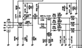
Thats another issue with your oscillator board. When you disabled the on-board oscillator, you disabled the clarifier too. Your oscillator board needs its own varactor diode :) Here is just the oscillator from the 959.
959 oscillator.png
This is why the viagra boards contain a varactor diode, to replace the function of the on-board varactor diode when the add-on oscillator is used.
 
Well I have decided to put this project on the shelf and find another problem which I will post in a few days.
Thanks to all who posted help and suggestions.
 

dxChat
Help Users
  • No one is chatting at the moment.
  • @ kingmudduck:
    Hello to all I have a cobra 138xlr, Looking for the number display for it. try a 4233 and it did not work
  • @ kopcicle:
    If you know you know. Anyone have Sam's current #? He hasn't been on since Oct 1st. Someone let him know I'm looking.