• You can now help support WorldwideDX when you shop on Amazon at no additional cost to you! Simply follow this Shop on Amazon link first and a portion of any purchase is sent to WorldwideDX to help with site costs.
  • Click here to find out how to win free radios from Retevis!

Galaxy DX-2547 low SSB output, help?

Adamf

Active Member
Jan 20, 2016
243
29
38
69
Hi all, so a while ago I posted about low output on my DX-2547 and was not able to get too far so I retested the radio today and find that on AM my output is about 3 watts dead key and swings to 17 watts or so which is fine but on SSB I can only get up to about 10 watts with full modulation, I used to get well over 20 watts. . I have adjusted VR13 but this is the best I can get. I have the dual mosfet IRF520's and I replaced them but no help and my AM output seems good so just an issue with SSB output. I do not have a scope but I have a good DVM and not afraid to test or try anything, any help out there?

Thanks for listening.

Adam in Florida
 

There are two ways to look at any "low modulation" condition.

Not enough power getting peaked

Or

There is too much power, so the peaks are flat-topping or boxcars.

To help more, would need a scope of the PRE-DRIVER output to the Driver - to see if the power output of one stage is too much and places a high gain stage (The Driver) into pushing too much power into the FINAL stage and making it appear as a power loss - when really the power loss is from too much input from a preceding stage.
Thanks, no scope as mnetioned was hoping someone had a similar problem and knew what component(s) it may be. Thanks, Adam
 
Ok, so we will approach another way.

Just using a finger or if you're into "RED LASER" pointers use a temperature gun to measure heat produced.

Check the Driver -
Check the Pre Driver (those two actually)

Measure in AM/FM modes - then again using some type of tone or feedback "squeal" from a MONITOR radio nearby BFO'd to the SSB frequency

Compare the two modes - SSB to AM (or FM) and see what "Steady State" does then go to SSB modes using low-level to high level admittance (acceptance) ranges - when you lose power - depending on the kind of loss it can help you determine the method or tuning requirements.
When I mention "Low-Level; to High-Level admittances (acceptance)"
It is referring to how well the stage amplifies the signal - if the stage takes in the signal and amplifies it greatly - non-linearly - the thermal issue comes up when you exceed the admittance window of the input - you're saturating - and Flat-topping of the signal is a result - then the loss is from the BANDWIDTH of the signal it is supposed to amplify is exceeded - so heat is the conversion of the bandwidth loss and power loss is the result even though it's supply has not changed.
The Low-level to High level is the dynamic range of the stages' ability to accept and produce power linearly.
IF your losses are voltage or frequency based - you'd get heating because the amplifier is generating a lot more power in SSB than in AM or FM modes - it's not really supposed to do that. Means too much of one thing is making the stage heat up - so is it needing a tune up or do you have a capacitor in the Emitter leg with TOO much capacitance and is considered "leaky" and now makes the stage produce more power over a wider bandwidth?

If one stage produces more power in one particular mode but not in the other - think about the modes - one is steady state carrier - while another uses linear amplification which is dynamic - so if one stage or even the audio amp sending the power to the mixer is not up to snuff - a scope helps correct this but again Heat or lack thereof - shows which section works and the one that doesn't is the one that is way off temperature wise in one mode - but in the other mode of steady state - the stage will rise and stabilize quickly - far faster than the others or not rise at all until a demand is placed on it.

One stage remains cool but the stage after is the one that gets hot?

  • Then consider the BIASING problem
  • - if the hot stage is using Class - A - (Example - Predriver)
    • - then suspect a bad resistor
    • - not always - but most cases the stage QUITS working due to a open resistor - not a drifting one - so this puts the open resistor on the LOW side - the one that drags down the voltage until it opens then the BIAS voltage rises and all bets are off
  • - while the positive rail one simply limits the current
  • - so if the biasing is off - a voltage check reveals this
    • - too low - the power rail resistor has opened,
    • - too high - the low side or divider side of the rail is faulty.
In Carrier modes, the Driver and FINAL stages usually get warmer than the Predriver ones - simply due to the Steady State demand of carrier - so they will heat up but it's the consistency of the heating "Shared" versus one predominates over others that reveals what stage is operating non-linearly.

Scope would make this easy, but heat is a tell-tale for many ailments and the scope would help in the type of ailment - but in this case the simplicity is in the component selection, you only have two - as the example of the Pre-Drivers own Emitter leg - Resistor and Cap - just go measure and correctly install the replacements of the faulty parts.

That is the best advice I can give you...
 
Last edited:
Ok, so we will approach another way.

Just using a finger or if you're into "RED LASER" pointers use a temperature gun to measure heat produced.

Check the Driver -
Check the Pre Driver (those two actually)

Measure in AM/FM modes - then again using some type of tone or feedback "squeal" from a MONITOR radio nearby BFO'd to the SSB frequency

Compare the two modes - SSB to AM (or FM) and see what "Steady State" does then go to SSB modes using low-level to high level admittance (acceptance) ranges - when you lose power - depending on the kind of loss it can help you determine the method or tuning requirements.
When I mention "Low-Level; to High-Level admittances (acceptance)"
It is referring to how well the stage amplifies the signal - if the stage takes in the signal and amplifies it greatly - non-linearly - the thermal issue comes up when you exceed the admittance window of the input - you're saturating - and Flat-topping of the signal is a result - then the loss is from the BANDWIDTH of the signal it is supposed to amplify is exceeded - so heat is the conversion of the bandwidth loss and power loss is the result even though it's supply has not changed.
The Low-level to High level is the dynamic range of the stages' ability to accept and produce power linearly.
IF your losses are voltage or frequency based - you'd get heating because the amplifier is generating a lot more power in SSB than in AM or FM modes - it's not really supposed to do that. Means too much of one thing is making the stage heat up - so is it needing a tune up or do you have a capacitor in the Emitter leg with TOO much capacitance and is considered "leaky" and now makes the stage produce more power over a wider bandwidth?

If one stage produces more power in one particular mode but not in the other - think about the modes - one is steady state carrier - while another uses linear amplification which is dynamic - so if one stage or even the audio amp sending the power to the mixer is not up to snuff - a scope helps correct this but again Heat or lack thereof - shows which section works and the one that doesn't is the one that is way off temperature wise in one mode - but in the other mode of steady state - the stage will rise and stabilize quickly - far faster than the others or not rise at all until a demand is placed on it.

One stage remains cool but the stage after is the one that gets hot?

  • Then consider the BIASING problem
  • - if the hot stage is using Class - A - (Example - Predriver)
    • - then suspect a bad resistor
    • - not always - but most cases the stage QUITS working due to a open resistor - not a drifting one - so this puts the open resistor on the LOW side - the one that drags down the voltage until it opens then the BIAS voltage rises and all bets are off
  • - while the positive rail one simply limits the current
  • - so if the biasing is off - a voltage check reveals this
    • - too low - the power rail resistor has opened,
    • - too high - the low side or divider side of the rail is faulty.
In Carrier modes, the Driver and FINAL stages usually get warmer than the Predriver ones - simply due to the Steady State demand of carrier - so they will heat up but it's the consistency of the heating "Shared" versus one predominates over others that reveals what stage is operating non-linearly.

Scope would make this easy, but heat is a tell-tale for many ailments and the scope would help in the type of ailment - but in this case the simplicity is in the component selection, you only have two - as the example of the Pre-Drivers own Emitter leg - Resistor and Cap - just go measure and correctly install the replacements of the faulty parts.

That is the best advice I can give you...
Thank you Andy for time spent on the answer. I'll print this out and see if I can handle this with my meager skills. I hate to ask, do you know which are the driovers and pre-drivers are? (SORRY). Appreciate it. Adam
 
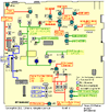
Just slightly modified the graphic...

1654481142435.png

Q 51 - so you know is the older 2314 DRIVER used in some CB radios from the 80's and 90's - the part runs in (those older CB radios' as) Class C and is about a 2W output device, but in this setup - the part is biased into Class A and is incorporated as a LINEAR Pre-Driver.

Q 52 is a 1906 - a part similar in power and function as the 941 used in older Cobra 29's and 25's - even Unidens version being the 76/78 and the 66/68 "PC" series radios. Used as a low-signal Pre-Driver, in this case - again Bias'ed as Class A incorporated. Just to bring it (signal) up so Q51 can do its job.

To help you in solving this - there used to be a discussion before about specific Galaxy radios that had parts omitted from the schematic (or X'd out) - or what I would call "Solving for X" - being a part that, if omitted, gives you a bloody mess but a lot of swing to the signal.

Putting the part in there - kept the radio from having a lot of swing - but also kept the neighborhood from having to contact you (in some cases - in no certain terms) and tell you to stay out of their stuff.

What I've suggested before is to put a resistor in-line (series) with the capacitor - as in one leg of it lifted - then one lead of a 330Ω ohm resistor soldered to that lifted leg, while the other end of the resistor is soldered into the hole where the capacitor leg came out of - forming a series circuit where you now have a means to adjust the level of feedback that controls the gain of this stage - allowing you to customize the results to a greater degree of performance, that you want.,

This is why it would help to have a scope for this process to be successful - so you can tweak the values to achieve the best peaking for SSB then all you have to worry about is a simple one-time adjustment to the FM and AM carrier signal level - and the rest - just runs...

The "Solve for X" part is the 3pF cap at C218, some radios even the one you have - did not always use a cap in C218's spot - so you know.
 
Last edited:
  • Like
Reactions: NZ8N
Just slightly modified the graphic...

View attachment 59258

Q 51 - so you know is the older 2314 DRIVER used in some CB radios from the 80's and 90's - the part runs in (those older CB radios' as) Class C and is about a 2W output device, but in this setup - the part is biased into Class A and is incorporated as a LINEAR Pre-Driver.

Q 52 is a 1906 - a part similar in power and function as the 941 used in older Cobra 29's and 25's - even Unidens version being the 76/78 and the 66/68 "PC" series radios. Used as a low-signal Pre-Driver, in this case - again Bias'ed as Class A incorporated. Just to bring it (signal) up so Q51 can do its job.

To help you in solving this - there used to be a discussion before about specific Galaxy radios that had parts omitted from the schematic (or X'd out) - or what I would call "Solving for X" - being a part that, if omitted, gives you a bloody mess but a lot of swing to the signal.

Putting the part in there - kept the radio from having a lot of swing - but also kept the neighborhood from having to contact you (in some cases - in no certain terms) and tell you to stay out of their stuff.

What I've suggested before is to put a resistor in-line (series) with the capacitor - as in one leg of it lifted - then one lead of a 330Ω ohm resistor soldered to that lifted leg, while the other end of the resistor is soldered into the hole where the capacitor leg came out of - forming a series circuit where you now have a means to adjust the level of feedback that controls the gain of this stage - allowing you to customize the results to a greater degree of performance, that you want.,

This is why it would help to have a scope for this process to be successful - so you can tweak the values to achieve the best peaking for SSB then all you have to worry about is a simple one-time adjustment to the FM and AM carrier signal level - and the rest - just runs...

The "Solve for X" part is the 3pF cap at C218, some radios even the one you have - did not always use a cap in C218's spot - so you know.
Hi Andy, again, thanks. So aren't we dealing with a bad part somewhere because it was putting out more? Are you suggesting that adding the 330 ohm resistors now could potentially fix the problem? Should I simply replace the 2SC1906 and 2SC2314F? Thanks again for hanging in. Adam
 
No, read the thread!

You start by finding the THERMAL profile - which section heats up

Does any section heat up?

IF no to one or the other - you're the one that is wondering why SSB power is low but AM and FM seem ok. You'll need to find out the WHY its doing this, then we can help you in the HOW to get it fixed.

Ok...? So why SSB only?

Well, you don't have a scope, so you ask about ideas - there are a plethora of them, but you seem to ignore others' advice...

You're not giving us the impressions that you are making the effort in searching for solutions - there is no easy answer when the thing works like this, but I want it to work like That scenarios - it's working, just not to your liking.
 
OK Andy, thanks, Adam
Andy, I used my thermal gun and not sure if this helps:

The IRF520 nearest to VR12 reads hotter, about 135 degrees. The IRF520 to the right of it nearer to VR10 reads 100 degrees.

Q51 reads about 100 degrees
Q52 reads about 90 degrees

Readings done after a minute or 2 of continual transmit.

Adam
 
In which mode AM/FM or SSB?

Remember in post #4 - two different "modes" - one steady state (carrier like AM or FM) then in SSB - the differences in the heating of the parts between both modes gives us the clues.

And since you're in MOSFET one, the biasing is different in the FINAL and DRIVER area - so let's profile the Pre-Drivers (52 and 51 first) to remove any doubt - then work on the input side of the Driver and Finals.
 

dxChat
Help Users
  • No one is chatting at the moment.
  • @ kingmudduck:
    Hello to all I have a cobra 138xlr, Looking for the number display for it. try a 4233 and it did not work
  • @ kopcicle:
    If you know you know. Anyone have Sam's current #? He hasn't been on since Oct 1st. Someone let him know I'm looking.