• You can now help support WorldwideDX when you shop on Amazon at no additional cost to you! Simply follow this Shop on Amazon link first and a portion of any purchase is sent to WorldwideDX to help with site costs.
  • Click here to find out how to win free radios from Retevis!

Galaxy DX99V2 low power and hot regulator

Lkaskel

Well-Known Member
Aug 4, 2017
420
349
73
60
Hi Everyone,
I have a 99V2 from a local op on the bench. It had a failed clarifier unlock issue. I completed the clarifier mod and aligned the PLL and it is now ok and on frequency. I noticed that the radio has one of the Palomar Max Mod regulators in place of the original. As I performed the TX alignment the regulator got VERY hot VERY quickly. Also, The max AM carrier is shy of 4 watts. I tested the driver and 2 finals and they all came back as FETs. The TX alignment went fine for the most part except for power out. The driver and finals adjusted to the correct ma and the SSB APC adjusted to 12.4vdc. Any thoughts as to why the low power or hot regulator? Should I just order new ones?

Thanks!!
 

so you have the IRF520 transmit section it sounds like?
the "0015" board.??

"driver and finals adjusted to the correct ma"

I was just working on a 2970N4, and on the main board,
with the three IRF520 design,
added the missing 100k ohm resistor so the driver bias
current can be set. (I have some posts in here on this)
but set 15 mA driver bias, and 50 mA bias
on each output FET.

and in AM mode, with a dead carrier, and around 5.5 to 6 volts
from TP7/8/9 to ground, the series modulation circuit,
"the regulator" dissipates half the power, so it gets warm
and hot after a while.

(p.s. - I removed the "swing mod" diode, so now I
also have proper AM on this radio. now I have to repair
the external amplifier.)
 
  • Like
Reactions: Shadetree Mechanic
so you have the IRF520 transmit section it sounds like?
the "0015" board.??

"driver and finals adjusted to the correct ma"

I was just working on a 2970N4, and on the main board,
with the three IRF520 design,
added the missing 100k ohm resistor so the driver bias
current can be set. (I have some posts in here on this)
but set 15 mA driver bias, and 50 mA bias
on each output FET.

and in AM mode, with a dead carrier, and around 5.5 to 6 volts
from TP7/8/9 to ground, the series modulation circuit,
"the regulator" dissipates half the power, so it gets warm
and hot after a while.

(p.s. - I removed the "swing mod" diode, so now I
also have proper AM on this radio. now I have to repair
the external amplifier.)
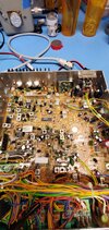
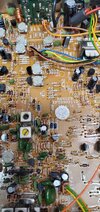
Thanks so much!! This radio has the 0011D board. I was using the alignment proceedures from the 98VHP (as recommended) as I could not find one specific to this radio. I can set the driver down to 15ma no problem. I expected the AM power to go from 10 watts down to maybe 1 but am only able to get 4 watts max. The fact that this radio is the 11D version does that change anything for you?
 

Attachments

  • 20240712_115913.jpg
    20240712_115913.jpg
    1.8 MB · Views: 8
  • 20240712_115920.jpg
    20240712_115920.jpg
    1.7 MB · Views: 8
I see the 010 schematic. about the same in the IRF520 RF
output section, and has the 100k resistor ("C291") in the driver bias
adjust circuit, so you can adjust properly.

and again, in AM mode, with a dead carrier, with your 4 watts out,
what is the voltage from TP7/8/9 to ground?

should be around 5.5 to 6 V.

and the total current into the radio at this time.

and does it modulate at your 4 watts carrier level?
whistle into that microphone.....

and you adjust that Max Mod part to 12.4 V for SSB,
so sounds like it is OK.
Well, I did a few things to the radio before I read this so darn!!!

I replaced the 520's with 3 new ones. I buy mine from Digikey so I feel confident that they are good. I got the same results. I also replaced the Max Mod with a brand new Tip36. Things are very strange now. The Tip36 is giving a 13.1 VDC so I think it is fine. The driver would only go down to 180ma. The 2 finals would adjust to 50ma separately but if I adjust 1 to 50ma and then the other to hopefully 100ma I would get a bad result. The adjustment would get to about 68ma and then jump to over 300ma. This is the case if I adjust the left or right final 1st. I get the same results. I then replaced the 2 VR's for the finals with new ones as a test. That made no difference. I tried 3 meters thinking that my bench meter was having issues. Nope, the same result. I did not mention this earlier but this radio was kitchen table modded by a previous owner. The Max Mod and everything turned up including the bias on the 520's that were in it. I'm used to getting radios like this. I know it just takes a little more effort to get them straight.

Thanks for any thoughts!!
 
  • Like
Reactions: Shadetree Mechanic
well, now your radio is all screwed up. but you can set the IRF520 bias
to 20 mA per device. as long as they are starting to conduct.

but check the bias voltage adjustments. in SSB mode, mic turned
off so no audio, no RF. with that mirror/shorting board in place,
key up, and turn each bias pot while watching the voltage at
the gate of each IRF520 and make sure it goes from zero to
around 5 volts. turn pot back and forth to make sure a smooth
change in gate voltage.
 
  • Like
Reactions: Woody-202
hey, hold off on your repair attempt. . . I have a Connex 3300HP
to work on. I got it working, real good. but I noticed about 5.7 amps
from the power supply during key up with 9 watts RF out.
this is not good. and that "regulator" transistor got so hot,
and it smoked and blew up!!! The 2970 main board I have here
draws about 6 amps also.
- so about 60 watts input, to get 8 to 10 watts of carrier,
so 30 watts of heat in the modulator/regulator transistor.

I have read all the posts on this regulator transistor getting
too hot problem. and some YouTube videos.

so gonna play with this 3300 here today.
 
OK, so this radio is fixed. Regarding the low power and regulator running hot I replaced the 3 520's and aligned it for voltage measured at the gate and not for current. The radio also had a VERY unstable frequency on AM. I had found that the slug in L20 was loose as the previous op had messed with it too much. I was able to get the slug to be tight again and the frequency is now good.
 
Some places say adjust by the voltage, most say current. I noticed that most radios perform exceptional when current biased. However, I have seen some radios, when current bias adjusted, fall flat on power output, way less than expected. Is that what you experienced? If so, did using voltage bias adjust correct it? I have a 3300hp right now that just won't output right with 50ma current each irf520 and all other things being equal.
 
  • Like
Reactions: Shadetree Mechanic
Some places say adjust by the voltage, most say current. I noticed that most radios perform exceptional when current biased. However, I have seen some radios, when current bias adjusted, fall flat on power output, way less than expected. Is that what you experienced? If so, did using voltage bias adjust correct it? I have a 3300hp right now that just won't output right with 50ma current each irf520 and all other things being equal.So, when I adjusted it current biased the power output was VERY low. Also, I had trouble with getting the current set correctly on the finals. I could adjust one final to 50mA
 
  • Like
Reactions: Cable Guy
I did have trouble when adjusting the radio using current bias. It had VERY low output power. Also, when adjusting it I could get one final set to 50mA and then when adjusting the second final I could get it to about 70mA total and then it would jump to over 150mA. It was VERY frustrating. Even if I left it at 150mA the power was still low. Now here is the thing I did not share as I try to avoid triggering anyone. Three years ago I had an opportunity to speak to a Galaxy tech in California. It was a very crazy circumstance but he reached out to me so I was really blessed that he would even talk with a "hobbyist" like myself. He was great to talk with regarding a radio I was working on and I was able to ask him about the debate over current vs voltage alignment. He did say that both would work but on Galaxy's behalf they were trying to keep folks from blowing the driver or finals and they may have missed it a little with the published alignment procedure. He said that IF the radio is in general good working order (not hacked) and the driver and finals were otherwise good, including their proper installation he would adjust them by measuring the voltage at the gate and go as high as 4.25vdc. I am always hesitant as I don't want to take something to the edge of their potential and have someone have issues due to bad swr's or something. With this radio I did use the voltage method, went to ~4vdc and the radio came alive. I know that it is higher than the recommended 3.65vdc max but,.....

That is where my expertise or understanding ends. I have aligned many radios with the dual final 520's using the current method and they work fine. I simply do not understand why occasionally it does not work and going higher does. I've never had an issue with an Anytone for instance. I do explain to the operator what was done and to just be careful. What I cannot seem to help is that many radios I work on get screwdrivered after the repair anyway.

Let me know how it works for you.
 
Went up to 4v on all gates, that brought the power up where a dual-final should be. I guess I will try current set first, and if power is weak, set by voltage. Thanks for posting that galaxy tech comment.
 

dxChat
Help Users
  • No one is chatting at the moment.
  • @ Jim5570091:
    Happy thanksgiving everybody. 73’s stay safe and GOD belle all of you!!!
  • @ Joseph23:
    Happy Thanksgiving to all and a very merry Christmas and a happy Newyear also. !!!!!!!!!!!!!
  • @ Moleculo:
    Congrats to GlocknSpiel for winning the Black Friday Radioddity QT60 Pro giveaway contest!
  • @ Deon:
    Good day, I have an Icom IC910H radio. I want to program a memory with split frequency tone on TX only and NO tone on RX,. Is this possible to do from the face of the radio? I don't have the interface to connect to a computer.
  • @ crappykraco:
    @Deon very unlikely to get a response here. You are better off starting a thread on the topic.