• You can now help support WorldwideDX when you shop on Amazon at no additional cost to you! Simply follow this Shop on Amazon link first and a portion of any purchase is sent to WorldwideDX to help with site costs.
  • The Feb 2025 Radioddity Giveaway Results are In! Click Here to see who won!

Galaxy Saturn growling noise from echo board

Hello,
I am sorry I have not been back for some time. I have been probing around on the Saturn and had discover TR42 was actually opened. Its a 2sc945.
I removed the bad one and popped in a new one and just like that the audio was back up and running loud.
The strange thing that puzzles me, until I look into it some more, it looks like that transistor should be for the receive audio.
Maybe someone who knows this radio better than I of course can shine some light on this area.
Also I found D83 cut for some reason. I wonder if this has something to do with by passing vr14 the modulation control on the board, because I have no control of VR14.
I have also found D68 cut and TR32 cut. TR32 is another 945 transistor. I had replaced these parts after fixing the audio issue, so I have no idea what these components do. I need to look back onto the schematic and try to follow the circuits I guess.

I am still looking into refreshing this radio where I can find where it is needed. Again I am sorry I have not returned until now. I am always out and about helping where I am able and sometimes I do not have time for myself.
I surly appreciate everyone here for their knowledge and their willingness to share their knowledge.

I wanted to at lease place this info on this particular post in case anyone else may run into this same situation. It was a strange one for me thats for sure.

RF Krazy
 
The value is written on your original variable pots. If they are dirty clean them with alcohol. If you can't see them cause they are too small, use a magnifying glass.
According to the schematic I posted which I am not sure matches your radio exactly the driver VR11 should be 1K, and the final VR10 closer to the antenna jack should be 100 ohm.
Hello all,

Well I don't know if anyone is up to helping with this radio again!

I finally replaced the final and the driver trimmers. I am now able to adjust
the driver (VR 11) bios to 20Ma. As for VR10 (50MA) one of the finals I am not able to adjust after replacing the trimmer pot. VR20 (100MA) I am able to adjust.
I did fine the RF mirror board fork like connection pin on TP9 with a bad solder joint. I re-soldered all three of those mirror board connections to play it safe, but I am still not able to adjust VR10.

The resistor that connects within VR10 that runs through a tiny ferrite core, that I think may be R216 but its hard to see through the components if that's correct? The resistors looks quite brownish as it may be burnt/open.

By looking at the schematic for VR20 and looking at R271 that also has the ferrite core and then looking on the schematic at VR10 with the resistor with the core, it appears to be R216 on the schematics.

My point to all of this, I was thinking that R271 for VR20 may be the same value
of R216. However R271 looks like 1st color Red, 2nd color Red, but the third color I cannot tell if it is Brown or Black and sometimes looks Gold in color, so maybe its actually Brown!

From what I can gather the schematic doe not tell the value of either R271 or R216.

Does anyone happen to know what this value may be? Also if R216 is truly open across the circuit, will this prevent the adjustment of VR10?

The R216 resistor pins that protrude through the board are a little difficult to see where they actually protrude. So I didn't want to attempt to remove it unless I am sure that this may be the reason I cannot adjust VR10.

I would like to add, the radio is putting out about 40 watts with good audio.
I am afraid that without having the one final bias adjusted that it could burn out the finals during transmit, and especially with an amp connected.

Sorry for the long read.

Thank you,
RF Crazy
 

Attachments

  • Output Trimmers.jpeg
    Output Trimmers.jpeg
    98.8 KB · Views: 6
Last edited:
Tip for better average swing on all the 3600 boards. Check/replace C133 (10uf 16v). I recommend replacing this cap with a 4.7uf 25v cap. This is the AMC Timing Capacitor. The factory 10uf is a little to aggressive (limits average swing). Also, strap a 22k ohm resistor across this caps leads on the bottom of the board.

Check/replace R174 and R187. Both should be 10k ohm each. If not, then replace with factory values of 10k ohm on each. I recommend for more mic drive to the mic op amp, replace these two resistors with 5.1k ohm each.

Check/replace the Passthrough regulator (big fat one mounted to right rear chassis), should be a 688 or 754. I recommend replacing with a 2SB817.

Check/replace the AF regulator (free standing transistor in front of Passthrough regulator). I recommend replacing this with a 2SA1012.

Check/replace the 8v regulator (looks just like a final mounted on right side chassis nearest the mic op amp - 4558). I recommend replacing this with a 2SA1012 also.

Replace TR32 limiter with another 2SC945. You can yank one out of an old parts radio, check it before installing though.

Check that R249 is intact. Should be a 10k ohm.

Check/replace TR53 AM only limiter, make sure it's intact.

Check FM tx audio. If it's weak, it's probably a diode shorted which could cause the growl issue.

Check/replace the three diodes across the front of the driver and finals. If one is bad, then I recommend replacing all three with 1N4001 (black diodes with silver/white stripe). These in my opinion produce a cleaner signal on the spectrum analyzer.

Replace both the two large 1000uf caps near the Passthrough regulator and audio IC to 2200uf 25v.

Replace the 330uf cap right beside the Passthrough regulator with a 470uf 25v cap.

Replace the 220uf cap nearest the mic on amp (almost in front of the 8v regulator) with a new 220uf 25v.

Replace the 220uf cap nearest the PLL, on the edge of the board (probably has wax at the bottom of the cap on the board) with a 1000uf 25v cap.

Check that there are no resistors/diodes tied to the Passthrough regulator leads on the bottom of the board, if so then yank it off.

To adjust bias:
1. Set radio to USB mode, no modulation (turn mic gain all the way down), with RF power all the way up.

2. Remove mirror board (bias plate).

3. Place ammeter to 200ma setting.

4. Place red prove of meter onto TP9. Leave this one here the entire time when setting the bias, you do not move this one until done setting bias.

5. Place black probe onto TP8.

6. Key radio. Adjust driver VR (adjustment to the left of driver) until you get to 30ma up to 50ma.

7. Unkey radio. Move black probe from TP8 over to TP7.

8. Key radio. Adjust first final VR (adjustment in front of first final) until you get to 50ma. Then adjust the last VR (adjustment in front of last final) until you get to 100ma.

9. Unkey radio. Remove ammeter probes from TP's.

10. Replace mirror board (bias board).

11. Turn mic gain up and key up on USB, then modulate. You should see between 30w up to 45w.

Now to set the carrier levels.
Find out what your max peak swing is by keying up on AM mode with RF power all the way up and modulation at 5 o'clock position (wide open).

Modulate. Then divide that maximum modulated swing by 4. Adjust the high key level (VR 14 or 16 I think) to 4 times lower than your maximum modulated swing.
Example:
RF power wide open, mic gain wide open, maximum modulated swing equals 40w, set highest key level to 10w.

Turn RF power all the way down, key up and adjust low key level VR (located on switch board behind switches) to 1w.

Turn RF power all the way up and recheck hi key level, readjust if needed. Then you'll have to readjust the low key level again. The hi key level VR adjustment affects the low key level adjustment, that's why you must go back and forth.

About forgot to mention, be sure the power supply voltage adjustment is set to 14.25v.

This should yield you about 45w to 55w PEP swing with some great average in AM mode.

Best practice is to replace all the electrolytic caps first, even the 50v caps.
 
  • Like
Reactions: Cable Guy
As for the growling noise, could come from several spots. My experience with the growling while the echo board was connected turned out to be a bad echo board which shorted out the mic op amp (4558). Bypassed the echo board completely, replaced the mic op amp and the growling was gone.

Hope the above helps out.
 
I basically just gave you (above) everything I do to these 3600 boards to get the max performance without harming other parts by heat buildup or creating any harmonics. Besides the alignment steps I go by. Tip: the VCO Buffers and oscillators are the trick (not secret) to receive and transmit audio sensitivity. We all have our own ways of doing things.

You're welcome to all.
 
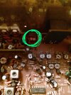
Also, this little coil in the rear is actually two coils butted against each other. Most people don't notice it as being two coils. These must be separated so as not to touch as seen in this photo. Yes, this coil does affect output. Closed = less, seperated in center only = more. Only seperated the two from each other, don't go spreading any of them, just seperate these two.
IMG_20250501_183632424~2.jpg
 
Had transmit audio feedback issues with old Saturn radios. Turned out to be the echo board. Inserting a 100 ohm resistor in line with the echo board's power lead and adding a 220uf cap from the board's power input to ground quieted them down every time.

But this was always a higher-pitched 'squeal', not a growl.

Go figure.

73
 
  • Like
Reactions: Hawkeye351
As for the growling noise, could come from several spots. My experience with the growling while the echo board was connected turned out to be a bad echo board which shorted out the mic op amp (4558). Bypassed the echo board completely, replaced the mic op amp and the growling was gone.

Hope the above helps out.
Hello Hawkeye351,

Thank you for the reply. I will continue to look over your helpful information and
study it to the best that I can understand, thank you.

The growling noise has been fixed along with plenty of transmit audio. The audio issue was the result of TR42, 2SC945, which looks to be a common part in this radio. The echo board is no longer installed.

The main issue at the moment is not being able to adjust VR10. As you had mentioned, the service manual states adjusting VR10 to 50ma. I cannot get the meter to activate at all when making any adjustments to VR10.

I replaced all three (VR) variable pots with new. 1K for the driver, and 100 ohms for the other two. R216 resistor looks very brown as if it is toast! But I am not totally sure if it is.

What would cause the issue of not being able to adjust VR10. I was thinking maybe this resistor R216, but I truly don't know. What is the resistor value as the schematic doesn't show what it is. I do appreciate your helpful information, as I look over the radio.

Rf Krazy
 
  • Like
Reactions: Hawkeye351
R216 should be a 1 ohm resistor. Also, are you sure the final that vr10 feeds is good? If a final is bad, you won't get any reading on your ammeter when setting bias. Check the collector voltage on the center lead of said final while keyed up (meter in volt mode).

R216 = 1 ohm (Brown, Black, Gold, Gold).
 
When a final transistor like that fails, it tends to short internally and dump 12 Volts from the collector circuit back the wrong way out the base terminal. This tends to blow out the bias diode. The voltage this circuit SHOULD put onto the base terminal of the final transistor is around 6/10 of a Volt. The transistor's manufacturing tolerances cause the exact voltage needed to vary. That's why VR10 is variable, not fixed.

If R216 is an open circuit, the diode and the trimpot are both suspect. Whatever current blew out R216 traveled also through those parts on its way to ground potential.

Dumbest day I remember with this task was to replace just the final. As you're seeing, can't get idle current with the trimpot, just stays at zero.

Sure enough, the bias diode is shorted. Can't get 6/10 of a Volt if a short circuit is in parallel with it.

Replaced the diode. Keyed the mike. Lights dimmed, fuse popped. As it happens, before the bias diode became a short, the voltage on the trimpot shot up high enough to blow out the trimpot. Now the 1-ohm resistor pops and the trimpot smoke stops.

Oh, and it wasn't kind to the new final transistor or the modulator transistor. Once they were replaced along with all that other stuff the bias trimpot would set the collector idle current just fine.

A few wasted bucks later.

But those are the lessons you don't forget.

73


Write your reply...
dxChat
Help Users
  • No one is chatting at the moment.
  • @ BJ radionut:
    NOTICE: The Midwest 6 Meter DX Group will be set up at Hamvention in Xenia...BOOTHS 9107-9111...COME SAY HELLO!
    +1
  • @ W4KVW:
    I mete KZ4RR there is 2013 for the 1st time & we live about 50 miles apart & had talked for many years. Traveled halfway across the country so we could finally meet. LOL W4KVW EM80wg
    +1
  • @ BJ radionut:
    Lee/KZ4RR will be thr at XENIA this year again...will be great to see him...We work almost every morning on 6m SSB
    +1
  • @ W4KVW:
    I will not be there but hopefully by the end of this month I will have my New tower and antennas back in the air including my M2 6M5X. The old tower and all of my antennas came down in October 2023 during a Hurricane.
    +1


      You do not have the permission to use the chat.