• You can now help support WorldwideDX when you shop on Amazon at no additional cost to you! Simply follow this Shop on Amazon link first and a portion of any purchase is sent to WorldwideDX to help with site costs.
  • The Retevis Holidays giveaway winner has been selected! Check Here to see who won!

Galaxy Saturn growling noise from echo board

RF Krazy

New Member
Dec 1, 2023
38
6
8
59
Hello,

Well after replacing finals from the help of some good folks here, I am getting this growling sound that is over bearing and knocking
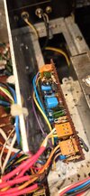
out my receive. By means of elimination of different circuits I discovered by removing either of the two top right hand jumpers
on the echo board this stops the growling. Of course this disconnects not only the echo/reverb but also disconnects the audio and the PTT.

I am not a fan of the echo board, but I would like to keep it inline with it working.

I tried to move the Frequency module (long metal box) away from the board and then even moved the echo board slightly from the frequency module thinking the noise from the frequency module was leaking onto the echo board.

I don't see any shielded audio wires coming onto the echo board either, which I find strange.

Would it pay to design a metal box around the echo board to see if this clears the growling noise?
Of course the Saturn was design to work as is even though it has some engineering defects from what the service manual states so to speak.

Anyone have an idea of what's causing this growling sound and maybe what can be done about it?

Thank you,
RF Krazy
I am not so sure its the echo board....

I removed the two top right hand brown connectors off the echo board and then inserted a very short wire to the two brown connectors after removing them from the echo board.

Picture the two connectors side by side laying flat next to each other. The inner pins which would be directly next to each other is where I inserted the short jumper wire.

This allow me to key the radio without going through the echo board. I did not reconnect any audio wires.

After making this connection, the growling cam back. I quickly keyed the mic and I was able to transmit. But as soon as I release the mic key the growl came back.

So just a guess with my way of thinking, I don't believe its the echo board
at all causing the growling???

Attached video and audio of the noise.

Any thoughts???

Again Thank you,

RF Krazy
 

Attachments

Last edited:
When I'm confronted with a symptom I can't explain, the place to look first is the power supply. This radio has two switched regulated 9-Volt power sources. This crop of the circuit board parts-placement diagram shows two bare jumper wires near the center of the crop.

4gL0JN.jpg


J26, the one towards the rear of the radio has the transmit-only voltage on it. Clip a DC Volt meter's black lead to the negative lug of the fat power supply filter capacitor behind the S-meter. Probe J26 while receiving. If you have a 'scope, this will reveal if any kind of noise waveform is present on this jumper. Should be zero Volts in receive mode. If a switching fault raises the voltage much past a half of a Volt it can disrupt the receiver circuits.

Likewise, see that you have at least 9 Volts more or less on J27 while receiving. Poking the 'scope probe here would reveal if your noise is coming from the switched power that feeds the receiver circuits.

I have seen a lot of radios with this circuit board, but this symptom is not a familiar one.

Best of luck.

73
Hello Nomadradio and thank you so much for your reply.

I have not taken any measurements as of yet, but I thought about a few things that may not be useful in the equation of this situation, but I thought maybe I should mention it anyway.

Originally and shortly after replacing the finals, my audio became low or not right in some way as I was told over the air.

And I knew the mic jack was loose and so I thought I better have a look at it.
I discovered the cap going from pin 1 to ground, that one side was disconnected. Also the ground lead from ground to pin 3 was also disconnected. So I removed all the wires and such excepted the small cap between pin 1 and pin 2. So that I could clean those connections up.

I tighten the mic jack and continued soldering the wires back onto the mic jack.
What I did not realize, I reverse pin 1 and pin 2. Well the audio was still not right. (Go figure)
When I realized what I had done, I simply reverse the wiring between pin 1 and pin 2 putting everything back as it should had been.

There after but not right away is when the noise crept in. I didn't think reversing those wires could effect the receive, but I thought maybe I should mention this anyway.

Anyway I will measure the voltage as mentioned and I will certainly report back.

I am gratful for your reply, thank you.

RF Krazy
 
When I'm confronted with a symptom I can't explain, the place to look first is the power supply. This radio has two switched regulated 9-Volt power sources. This crop of the circuit board parts-placement diagram shows two bare jumper wires near the center of the crop.

4gL0JN.jpg


J26, the one towards the rear of the radio has the transmit-only voltage on it. Clip a DC Volt meter's black lead to the negative lug of the fat power supply filter capacitor behind the S-meter. Probe J26 while receiving. If you have a 'scope, this will reveal if any kind of noise waveform is present on this jumper. Should be zero Volts in receive mode. If a switching fault raises the voltage much past a half of a Volt it can disrupt the receiver circuits.

Likewise, see that you have at least 9 Volts more or less on J27 while receiving. Poking the 'scope probe here would reveal if your noise is coming from the switched power that feeds the receiver circuits.

I have seen a lot of radios with this circuit board, but this symptom is not a familiar one.

Best of luck.

73
Hello,

Well I am scratching my head on this one.

I placed the volt meter on J26 and indeed it was zero volts in the receive mode.

I then checked J27 and it had 8.5 volts on it.

Incidentally I have had the echo board removed a few times, trying to figure
where the growl was coming from. I think I had mentioned if I disconnect the two top jumpers on the echo board, the growl would go away. Actually either jumper being disconnected would stop the growl.

I have also found that the frequency display would go out at times. By pressing on the top wires on the module the display would reappear. You can tell this radio has been in a few hands or at lease one terrible hand! My may not being much better?

Anyway having the echo board disconnected and then reconnected as well as the frequency module, the growl had gone away. However I had transmit but no modulation.

During this time sitting here and typing I had the radio on and listening to the locals. Out of the blue the receive started that growl sound again and all of the sudden it stopped and everything got quiet, meaning no receive. I looked down at the face of the radio and I see that its keying up, meaning its in transmit and there is no mic connected. I noticed the wattage on the external watt meter was peaking at lease 30 some odd watts. So there must had been a squeal of some kind going on too.

Of course I turned the pwr switch off immediately. I am baffled with what's going on here. I have never ran into this before. I am sure my mic wiring at the jack is correct, but I will be having another look at that too, because it seems that is where everything had started.

Confused? Yes! I don't know what's going on...

RF Krazy
Okay, mic jack looks fine.

I disconnect the two brown connectors again from the echo board. The receive sounds fine and it didn't go into transmit.

However, I took a small wire and created a short jumper and placed it across
the yellow and orange wires in the two brown connectors after removing them from the echo board.

When doing so the radio goes into transmit without the mic connected.
So there has to be a short at this point somewhere along the PTT.
This isn't to say this will fix the growl after finding the short.

I have also found two pins of the TR32 cut from the board.
I found this to be the AMC shunt switch 2SC945AQ. I believe this
is some audio Amplifier of sorts.

Still zero volts on J26 and 8.5 volts on J27 with the brown connectors removed from the echo board.

How does the echo board get by-passed? I think I would like to by-pass this for now just to keep it simple. (KISS) Me being the letter S at the end!

This is as far as I had gotten so far...still poking around.

RF Krazy
 
Last edited:
What are the voltages at the 4558? It serves as a tx switch and mic amp, being common to both functions you are having issues with. I think it's IC4. That is where I would go.
 
What are the voltages at the 4558? It serves as a tx switch and mic amp, being common to both functions you are having issues with. I think it's IC4. That is where I would go.
Hello Cable Guy and thank you for chiming in.

Okay here is what I measured. Factory voltages to the left, mine are to the right.

1) 4.57. ---- 4.40
2) 4.58 ---- 4.50
3) 4.58 ---- 4.50
4) 0 ---- 0
5) 4.51 ---- 4.47
6) 3.33. ---- 3.33
7) 7.74 ---- 7.62
8) 8.43 ---- 8.31

Mine are a little low, but ???

Again, thank you, I appreciate the help as always.

I am puzzled how this radio has gone down so to speak.

RF Krazy
 
Last edited:
I assume that's with the echo disconnected and your little jumper removed? So, when everything is wired correctly, it auto tx's? What are voltages when it's auto tx'ing? I'd remove the mirror board while troubleshooting so you're not passing through to the PA sections. I'm thinking fix the newest symptom first, the stuck key, and since both symptoms share that dual op-amp circuit, IC4, that would be a good starting point if i were tasked with this. Fwiw, I'm not a tech, I'm a hobbyist, but I haven't blown up a radio in quite a few years so... I will help if I can, and sandbag if I can't.
 
I assume that's with the echo disconnected and your little jumper removed? So, when everything is wired correctly, it auto tx's? What are voltages when it's auto tx'ing? I'd remove the mirror board while troubleshooting so you're not passing through to the PA sections. I'm thinking fix the newest symptom first, the stuck key, and since both symptoms share that dual op-amp circuit, IC4, that would be a good starting point if i were tasked with this. Fwiw, I'm not a tech, I'm a hobbyist, but I haven't blown up a radio in quite a few years so... I will help if I can, and sandbag if I can't.
Well for a Hobbyist, your doing well on your thinking.

Without the mirror board installed, and everything connected and the radio
in transmit, here are the voltages. Factory Voltages on the left and mine on
the right.

1) 4.54. --- 2.57
2) 4.54. --- 2.58
3) 4.55 --- 2.59
4) 0. ---- -01.91 < Negative -01.91
5) 2.25 --- 1.45
6) 3.31 --- 1.41
7) 2.46 --- 4.32
8) 8.38 --- 6.40

I'm thinking they could be a bit lower if the mirror board was installed, drawing
more current from the supply...

There has to be something shorted on the transmit side now?

I starting to learn some of the paths on this radio anyway.

Does anyone know how to by-pass the echo board?

Again thank you Cable Guy.

RF Krazy
 

Attachments

  • Echo Board.jpeg
    Echo Board.jpeg
    88.6 KB · Views: 5
Last edited:
Does anyone know how to by-pass the echo board?
Yeah, I bypass it like you tried to do it, using jumpers if i want to keep the connectors for reinstalling later. You are creating a mic/ptt pass-thru with the jumpers. Let me check my notes on that and pour over the voltage readings.
 
Oh, on another point, this chassis is getting old. I usually recap a radio like this after getting it going, if I plan on putting my seal of approval on it. I'm wondering, did these issues surface after soldering? Are you unplugging the power to the radio when you solder? I ask because I have seen things. That's all.

Oh, some pics would be just great.
 
I would try operating the radio without it's on-board power supply. Leave the unit unplugged, the power switch OFF, and connect a good 13.8 VDC supply to the Red (+) wire going from the on/off switch to point # 22 on the main board, and the (-) supply wire to a suitable ground point. If the growling noise goes away, then the noise is being generated by the power supply. If the noise is still there, at least you've eliminated the supply as the culprit.

- J.J. 399
 
Oh, on another point, this chassis is getting old. I usually recap a radio like this after getting it going, if I plan on putting my seal of approval on it. I'm wondering, did these issues surface after soldering? Are you unplugging the power to the radio when you solder? I ask because I have seen things. That's all.

Oh, some pics would be just great.
Oh my gosh. Seriously...

I hate to admit something as bad as I am going to admit, but I have a large
quantity of egg on my face. I am being totally serious, and I am deeply sorry
for the time I am taking up here.

After looking at the mic jack, and I mean after a few times, something
kept poking at me about it.

When the mic jack had come loose and broke some connections, I thought
I had seen where the soild ground wire had went to pin 3. There is suppose to be a small cap to ground, but it is not present. Another issue I am finding out, not all mic jack are totally the same.

So the point I am making is, I soldered the solid ground wire to pin 3.
Pin 3 to ground is how it it is keyed. I started thinking more of this and I thought to myself it has to have something to do with what I had last done to the radio.

I looked at that mic jack at least a half a dozen times and I thought it was correct every time I looked at it.

I am deeply sorry. I mean how could I had been so stupid? Grrrr...And no pun on the growl either.

Well I am still not out of the woods. I must had blown something in the audio chain, because now I have no audio/modualtion.

My voltages on IC4 (Op Amp) are a little
closer to the specs now. Even on transmit with the mirror board installed.

(With Mirror Board installed) Factory Specs on Left side
Transmit Voltages. RX Voltages
1) 4.57 --- 4.50. --- 4.54 --- 4.49
2) 4.58 --- 4.52. --- 4.54 --- 4.50
3) 4.58 --- 4.52 --- 4.55. --- 4.49
4) 0 --- 0. --- 0. --- 0
5) 4.51 --- 4.48. --- 2.25. --- 2.24
6) 3.33 --- 3.34 --- 3.31. --- 3.32
7) 7.74 --- 7.65. --- 2.46. --- 2.47
8) 8.43 --- 8.34. --- 8.38. --- 8.29

What is strange, everything worked for several hours before it acted up???

Anyway now I am wondering if the audio isn't passing through the echo board.
I can jump the PTT but I don't know what wires are the input and output to jump to one another. I thought I knew when I had tried earlier, and I am thinking maybe that is how I actually blew a component by trying to connect the input and output when I wasn't 100% sure they were the correct ones? The service manual shows a different echo board then the one I have in this unit.

For shins and grins, I try the audio with the echo turned on, button avail.

Man I am sorry for wasting everyones time.

RF Krazy
 
Oh, on another point, this chassis is getting old. I usually recap a radio like this after getting it going, if I plan on putting my seal of approval on it. I'm wondering, did these issues surface after soldering? Are you unplugging the power to the radio when you solder? I ask because I have seen things. That's all.

Oh, some pics would be just great.
Hello Cable Guy,

Everything seem okay until the finals blew. After replacing the finals, the mic jack
was loose and a couple of connections broke. Apparently this was what really started all the conflict. And yes I would unplug the radio and then turn it on to drain any excess voltage from the circuits, and do my soldering from there.
I don't know how I had over looked that ground wire.

I can only hope that maybe someone has the schematics for the echo board that I am using. I am starting to think the audio isn't passing through the echo board.

I really don't know what wires are the input and the output to join them together away from the board. I would think the in and out wires would have mini like coaxial audio type wires, but they don't. Not very good shielding thats for sure.

Just the same, thank you for helping.

RF Krazy.
 

dxChat
Help Users
  • No one is chatting at the moment.
  • @ Crawdad:
    One of the few times my tiny station gets heard on 6m!:D
  • @ Galanary:
    anyone out here familiar with the Icom IC-7300 mods
  • @ Crawdad:
    7300 very nice radio, what's to hack?
  • @ kopcicle:
    The mobile version of this site just pisses me off
  • @ unit_399:
    better to be pissed off than pissed on.
    +1