• You can now help support WorldwideDX when you shop on Amazon at no additional cost to you! Simply follow this Shop on Amazon link first and a portion of any purchase is sent to WorldwideDX to help with site costs.
  • Click here to find out how to win free radios from Retevis!

Grid-driven Tetrode Input Circuits

Naysayer

Solder Balls
I Support WorldwideDX.com!
Mar 6, 2020
252
196
53
New York
Been winding Baluns, tidying messy wires & tweaking this & that. Replaced the small core with 1-1/8" core (still mix 43). I'm focused on the RF Input section now. Changes take time to try and what works on a DL is not always good on an antenna.

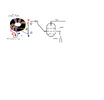
The attached "now" pic file is a diagram of the Input that is working best so far. Max drive is mid-20w's pep on 40. <12w pep on 10M. I'm not content with only 1 balanced output feeding the tubes. Feel like I'm wasting half my drive. I'm looking for some suggestions/criticism. Unfortunately, my test equipment is limited to an swr analyzer but I've come a long way. Input SWR is nearly perfect from 10-80 and the tank pi shows optimal settings in the mid-range of each component so I can fine tune. (Mr. Hacksaw removed some air cap plates) 40M PO is impressive, >kw pep easy with <30w drive.

To swap tubes I placed a toggle to switch Grid Bias and the multi-tap Screen Transformer has bullet connectors so I can swap secondary terminals from 350v or 400v. It's far from fast but do-able in about an hour. 10M performs the worst. If I short the tank coil & switch for just 10M, the PO goes up a lot, so it comes with multiband territory, I guess. These tubes are tougher than I expected. I made a few mistakes that did not yet destroy the tubes (leaving blower Off, etc). I need an Idiot Light for the Blower so that means...... IDK. I re-adjusted Buck-Boost for lower plate voltage & got a bit more usable plate current so progress continues just slow.

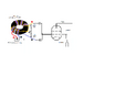
Back to RF Input, I'm trying to decide what circuit to try next. I think there's more efficiency to be had extract from the balun/swamped resistance arrangement. With one balanced lead going to RF ground I'm losing almost half the drive. the plan is to try connecting the other output ...... somehow. The other diagram is my next attempt as of now.
neil, NYC
 

Attachments

  • Balun Input now.png
    Balun Input now.png
    80.2 KB · Views: 171
  • Balun Input next try.png
    Balun Input next try.png
    80.2 KB · Views: 155
  • Like
Reactions: AudioShockwav

Thinking back to the Pride DX300 input circuit. The control-grid's capacitance prevents the 10-meter input from being resistive, even with swamping resistors as shown. The Pride deals with this by putting a toroid inductor across the grid. The inductance is chosen to 'cancel' the grid's capacitance and become broadly resonant across the 10-meter band. Lower bands require an added capacitor to resonate those bands' grid coils. So long as you have a broadly-resonant parallel tuned circuit across the grid-swamping resistors, the input impedance remains largely resistive.

That amplifier uses an untuned 3-to-1 voltage step-up transformer wound trifilar on a toroid core. Never have discovered the ferrite type they used, just bought them from RF parts as needed over the years.

Takes very close to 1 uH to get the input SWR down on 10 meters with a 250B tube. I'm feeling too lazy to look up the 300's grid capacitance just now, but you get the idea.

I know we tried using a transmission-line style input transformer on a 250B tube decades ago. What I remember was that it required a trimmer cap from the its output to ground. It was sufficiently long ago there are probably no bench notes about the setup.

I'll admit to being a bit puzzled over the diagrams. Only one end each of the red, blue and yellow wire is show. I would ground the 'start' end of the blue, connect 'finish' end of the blue to the start end of the red wire. This will be the 50-ohm input. The finish end of the red goes to the start end of the yellow. The finish end of the yellow will be your 450-ohm output to the tube grid and swamping resistor. This is how the trifilar step-up toroid in the DX300 is built.

73
 
  • Like
Reactions: Naysayer
Thanks for your time to comment. I need to re-read your first para a few more times to fully understand it but I will do so. The very idea of a transformer for RF is fascinating.

I looked at the Pride input on paper but could not decipher the diagram. Think I need to see the part, visual search online I guess.
Adding Capacitance, sounds like a good idea. Wish I thought of that before I closed up. I'll investigate that next. Amp is buttoned-up now so next time I open it up I'll have another go at it.

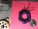
The drawings were meant only to show the different connections on the balanced outputs. It's an ordinary 50:300R balun with a Star and Dot to show polarity. The attached pic is a close-up of a 'practice balun' just like it except I used different wire. The 2 middle wires (twisted pairs) are 50R input & the 2 outside wires are the outputs. Works good 20-80 but my 10 problems could be most anything,

Edit
I get you now: "10M on these tubes is notorious for Input Capacitance issues".
That provides direction. Thanks Nomad.
Later,
Neil, NYC
 

Attachments

  • 6 to 1 Balun.jpg
    6 to 1 Balun.jpg
    1.1 MB · Views: 147
Last edited:
Thinking back to the Pride DX300 input circuit. The control-grid's capacitance prevents the 10-meter input from being resistive, even with swamping resistors as shown. The Pride deals with this by putting a toroid inductor across the grid. The inductance is chosen to 'cancel' the grid's capacitance and become broadly resonant across the 10-meter band. Lower bands require an added capacitor to resonate those bands' grid coils. So long as you have a broadly-resonant parallel tuned circuit across the grid-swamping resistors, the input impedance remains largely resistive.

That amplifier uses an untuned 3-to-1 voltage step-up transformer wound trifilar on a toroid core. Never have discovered the ferrite type they used, just bought them from RF parts as needed over the years.

Takes very close to 1 uH to get the input SWR down on 10 meters with a 250B tube. I'm feeling too lazy to look up the 300's grid capacitance just now, but you get the idea.

I know we tried using a transmission-line style input transformer on a 250B tube decades ago. What I remember was that it required a trimmer cap from the its output to ground. It was sufficiently long ago there are probably no bench notes about the setup.

I'll admit to being a bit puzzled over the diagrams. Only one end each of the red, blue and yellow wire is show. I would ground the 'start' end of the blue, connect 'finish' end of the blue to the start end of the red wire. This will be the 50-ohm input. The finish end of the red goes to the start end of the yellow. The finish end of the yellow will be your 450-ohm output to the tube grid and swamping resistor. This is how the trifilar step-up toroid in the DX300 is built.

73
The grid inductance you describe is series inductance right?

It was inevitable that after amp basics in place, I would need to re-visit 'inductance in the grid circuit'. I got lucky here and there but it's time to address this. Thank you for quantifying it around 1uH Nomad. Thats a good start. Been winding coils to get a feel for 1uH. Small-ish, 7-8 turns ballpark (on 43/140 Toroid & without). Trick will be switching it in and out but can deal with that later.
I'd settle for PO on 10 and figure out switching later.

Edit 1: Scrapped all the caps & resistors I had from 1st matching attempt. Now have simple 1:6 balun with one, 300 ohm NI resistor across balanced outputs. Short wire from 1 balanced output to capacitor to New coil to tube grids. Coil is 1/2" diameter 7T 18 gauge magnet wire (best I could estimate to 1uH using cheapo meter).

Trying to replicate coil pictured in the single tube RF Deck below (K2VCO at: https://www.qsl.net/k2vco/4CX1000A/K2VCO 4CX1000A Amplifier.html)

Edit 2 The insertion of inductance between capacitor and grid did not do much for 10/20 but seemed to help 40. Nothing to really measure. So onto the next approach: I have 2 tubes so I can use a toroidal inductor to connect both tubes on the other side of the socket from where RF is fed. Such an arrangement can't hurt & may even help to the extent it qualifies as "placing an inductance across the grids"
to be continued
 

Attachments

  • Grid inductance.png
    Grid inductance.png
    1.1 MB · Views: 103
  • RF Input 6-24.JPG
    RF Input 6-24.JPG
    1.9 MB · Views: 95
Last edited:
Edit 3: In for a penny in for a pound.
Ordered a better Inductance meter. 1 uH is so small.

Removed Edit 2 coil and reattached lead to grid from balanced output. Installed inductor across grid terminals on other side of tubes. I need to measure with more accuracy than I can now. Meter coming from nearby so time to take a break for few days.
 
The coil we use on one 250B grid is 1 uH or slightly less. Rewinding the original 11 turn factory toroid to 13 turns moves the resonant frequency down to around 28 MHz. Close enough for 10 and 11 meters both. Years ago I wondered about the input impedance of the Pride. Hooked the antennal analyzer to one and keyed it. Found that lowest SWR with the factory circuit was almost 30 MHz. Odd. Adding more inductance brings down the resonant frequency, but now the input SWR was high, but resistive.

Decided that the original grid swamping resistance of 750 ohms didn't make sense to me, so ever since I have used four 470 ohm resistors in series/parallel to put 470 ohms in parallel with the grid. A 3-to-one step up ratio in the input transformer should provide a nine-to-one impedance ratio, closer to 470 than 750.

If we feed RF into the grid without the coil with just swamping resistors in parallel with the grid circuit, the impedance will reflect the grid's parasitic capacitance in parallel with the resistors. Raises the input SWR and makes it reactive. Cancelling this capacitance with a parallel inductance makes the input resistive again.

My strongest suspicion about the factory using too much resistance and too little inductance in the grid circuit was meant to increase the RF drive voltage to the tube grid, and make the wattmeter as happy as possible.

45 years later, even a wimpy radio puts out half-again more than the 1970s radios it was meant to be used with. Even with the setup we favor the tube starts to show excess drive symptoms around the 18 or 20 Watt peak range. Not worried about cutting down the drive sensitivity.
 
  • Like
Reactions: AudioShockwav
Thank you for the feed back. I got some 10M gains by placing a roughly 1uH inductor across the grid connecters on other side of socket last night. 20 still dead and 40 always good. The added inductor connected the 2 grids together and was Parallel to the RF drive connection on other side of sockets. Series would be in the RF drive path. Which is better?

uH meter coming in a few days. Will look at Pride input again to better understand what you write.

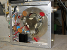
I have a 4 slug tuned coils from a Collins amp. There is already a 1/4" hole between the tube sockets and I'm thinking.... adjustability is nice. I've been driving the 2 tubes as if they were 1 by connecting the grids together with solid wire & driving the wire. RF Input 2 6-5-24.jpgAny advantage from using separate low value resistors to each tube or is that unnecessary?
 
  • Like
Reactions: AudioShockwav
It's been over a year since I looked at Pride diagram and it feels good seeing it again with more experienced eyes. The cap & inductor pairs to ground switched in parallel to a direct grid driving connection post resistive ground is curious. I expected an all or nothing switch-action but the diagram shows a direct connection from resistive load to grid no matter what band is selected. Resistive and Inductive parallel to each other to RF ground. I think I get it.

Curious swamping R's (2x 1500 resistors) goes to ground via capacitor through bias choke. Edits writing helps me figure it out.
 
Last edited:
That manual was the work of the guy who started the first CB Tricks web site, Bennie.

He asked me about the inductance values of those coils, since the factory book offered no guidance. I had a spare relay board, so I took the coils loose and measured them. There is some of my material in that book, but the bulk of the work to produce it was Bennie's not mine.

73
 
  • Like
Reactions: Naysayer
CB Tricks was the place for a long time.

RF Parts sells the 1:9 toroid from old Pride stock so I ordered one plus an assortment of fixed, factory-made inductors. I can also wind my own as I try to copy the Pride input but for 2 tubes. As for the Pride RF Input, there’s a lot to respect given how the Resistive padding runs parallel to band-switched inductors, because:

The swamping resistance (from two 1500Ω 2w resistors in Parallel) sums to 750Ω not the 450Ω the 1:9 toroid (50 to 450) is looking for. To get 750Ω down to 450Ω a whopping 1125Ω is needed. Very little resistance from the switched inductors so what brings the 750 down to 450?
----------
EDIT: Apparently, I need to factor in the resistance of each of the 4 inductors for 10/11, 20, 40, 80)
----------
IDK yet but it brings the added inquiry of what affect will come from 2 tubes instead of 1? The 300a's should be close enough to work with Nomad's 250b/Pride uH specs.

I will copy those inductance values and report back. Some use value from your efforts. Nomad, you contribute a lot to the Amateur community, thank you.
 
Last edited:
  • Like
Reactions: AudioShockwav
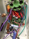
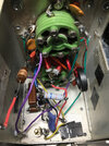
Removed everything from inside Tube deck, starting fresh. Added terminal strip and ceramic post as foundation for mounting components. Will duplicate Pride input circuit best I can. Have picture of pride Input board to aid in part selection. Have good selection of red & yellow toroid cores to use Turn count for starting point & Inductance meter to verify. Ordered two, 200uH Bobbin chokes as pictured on the Pride input board lower right corner. Only concern I have at this point is what affect an extra tube will have.
 

Attachments

  • DX-300 Input 2.jpg
    DX-300 Input 2.jpg
    115.5 KB · Views: 72
affect an extra tube will have.


Higher shunt capacitance in the control-grid circuit.

The 10-meter coil will probably need a couple fewer turns for two tubes than for one. The lower bands might need the shunt cap for that band reduced some.

The lower the band frequency the less difference this will make. The 80-meter input for the Pride is untuned, consists of a choke coil. The shunt capacitance the radio will be feeding into has such a high reactance at 3.5 MHz that a coil to cancel it out is not needed to obtain a good input match. Odds are this rule holds for the two-tube setup.

An antenna analyzer on the input once it's tuned up will reveal where the frequency where the input SWR dips to its lowest.

73
 
  • Like
Reactions: Naysayer
Thank you Nomad, wonderfully specific. Diagram shows 10 & 39pF shunt caps for 20 & 40M. Given that 2 tubes is twice 1, is halving the values (to 5 & 20pF) overkill?

Someday I'd like to be able to recognize these concepts by sight instead of only copying them. Thank you again.
 
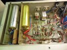
Stripped RF deck down to sockets. Rebuild looking better than my prior mess which worked great on a DL, lol. Antennas not so much. The 3 PSU's (plate, grid, screen) are in order so back to revising RF Input with an attempt to copy Pride's diagram for 10-11-20-40.

Received a better Inductance meter, LC100-A Ver 4.8. Using some quality fixed inductors I found the meter useless below 1.4uH. It's good for higher values and does provide a sense of what a few turns actually means in circuit. Back to counting Turns and 'designing for less' so whatever uH value I'm searching for will likely be more. That gives me a probable direction to follow (adding uH easier than removing).

Getting hot in NYC and it's not even July yet.
Will post more soon. neil
 

dxChat
Help Users
  • No one is chatting at the moment.
  • @ BJ radionut:
    EVAN/Crawdad :love: ...runna pile-up on 6m SSB(y) W4AXW in the air
    +1
  • @ Crawdad:
    One of the few times my tiny station gets heard on 6m!:D
  • @ Galanary:
    anyone out here familiar with the Icom IC-7300 mods
  • @ Crawdad:
    7300 very nice radio, what's to hack?
  • @ kopcicle:
    The mobile version of this site just pisses me off