
You are using an out of date browser. It may not display this or other websites correctly.
You should upgrade or use an alternative browser.
You should upgrade or use an alternative browser.
-
You can now help support WorldwideDX when you shop on Amazon at no additional cost to you! Simply follow this Shop on Amazon link first and a portion of any purchase is sent to WorldwideDX to help with site costs.

Ground mounted cb vertical antenna
- Thread starter nfsus
- Start date
Quaterwave whip. Put it on the ground, add as many radials as you can. I would not go lower than 32.
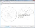
Performance depends on ground (counterpoise) quality and antenna location. Should be fine on top of the hill without any obstacles around. Radiation pattern in attachment.
Basically you can put any antenna on ground level, but it needs good counterpoise.
Mike
Performance depends on ground (counterpoise) quality and antenna location. Should be fine on top of the hill without any obstacles around. Radiation pattern in attachment.
Basically you can put any antenna on ground level, but it needs good counterpoise.
Mike
Attachments
Last edited:
I built a vertical using bamboo pole with some 16 gage wire tye wrapped to the pole and a few(not enough) radials out of the same wire. Wasn’t much for working local but worked ok when the band opened up. It was cheap and it got me on the air.
Keep in mind that radials/counterpoises, mounted 90 degrees to the radiator, gives you an impedance of 37 Ohms, so even at resonance, the lowest possible VSWR is 1.5:1
However, you can raise the impedance by offsetting the feedpoint, make your radiator longer, and your radials shorter, and you can experiment with lengths by using only 2 radials, once you find the best VSWR for where you want the "center" of your antenna's tuning, you can add more radials. Also, use ferrite to choke your coax at the feedpoint, that will go a long way to improving your VSWR.
One downside to a 1/4 ground plane antenna however is the amount of energy put into the ground...if you have the ability to make a coil and buy a capacitor, you can make an end-fed 1/2 wave vertical. You can calculate an impedance matching circuit here:
Presumably, your input is 50 Ohms, and your impedance of the end-fed 1/2 wave will be about 2400 Ohms or less, close to the ground; plug in your "center" frequency, and see the circuit design, and the two components you need, and you can make adjustments to the coil you make to fine tune your VSWR. The nice thing about an end-fed half-wave, is no radials are needed, so less energy into the dirt/ground.
However, you can raise the impedance by offsetting the feedpoint, make your radiator longer, and your radials shorter, and you can experiment with lengths by using only 2 radials, once you find the best VSWR for where you want the "center" of your antenna's tuning, you can add more radials. Also, use ferrite to choke your coax at the feedpoint, that will go a long way to improving your VSWR.
One downside to a 1/4 ground plane antenna however is the amount of energy put into the ground...if you have the ability to make a coil and buy a capacitor, you can make an end-fed 1/2 wave vertical. You can calculate an impedance matching circuit here:
Certainly doable but the high number of ground radials needed makes it quite a chore. Can't you elevate the antenna off the ground any at all?
Keep in mind that radials/counterpoises, mounted 90 degrees to the radiator, gives you an impedance of 37 Ohms,
I'm curious as to where you got this idea, its at least the second time I've seen you post this. The problem is, it isn't true.
If a 1/4 wavelength vertical antenna is over a perfect ground, then it will have 36 or 37 ohms of impedance. But four radials does not a perfect ground make.
The impedance will be lower, perhaps 20 to 25 ohms. If you are seeing a 1/4 wavelength antenna above four 1/4 wavelength radials get you 36 or 37 ohms, it is because other things are also effecting the antenna, such as the height above the earth, and the quality of the earth itself. Common mode currents is another common one. These are variables that change from install to install.
The DB
Last edited:
over a year ago, this local CBer gave me this old Antron 99,
that has been painted, and it suffers from "erectile dysfunction"
as the thread is stripped up at the top section.
I just slapped it up on at this 4 by 4 wood pillar from an old
decking in my backyard, on a five-foot section of metal pipe,
with a length of LMR400 coax, just to get on the air to talk on CB,
and maybe try 10 meters.
and here in southern Louisiana, with our conductive moist
dirt ground: it works great for DX. with a HR2510
with about 8 watts on 29.6 MHz FM, I made it to Panama,
Columbia, etc. Then last winter on 29.6 MHz FM with 120 watts
from a RM Italy amplifier that I repaired and the HR2510,
I was having a blast, talking to Southern California each morning,
and the repeaters up near Toronto. And also making it to
Japan, Brazil, New Zealand, Australia, etc. One time I was just
messing on 29.000 MHz AM with this RM Italy KL-300p amplifier
(Not a RF Linear amplifier, no bias circuit) and my friend Roger
in New Zealand heard me. He was monitoring the AM calling freq
and caught me messing around with my distorted AM signal
from the RM "linear amplifier." about 40 watts carrier.
and I use it on CB. there is a local gang around here
on ch. 20 AM, and on 27.415 MHz LSB, channel "41"
so the metal mast is the counterpoise, or other side
of the antenna. I had it on a 10 foot pipe at first, which is
a good counterpoise for it. but I put it on a 5 foot
section so that I can mess with the tuning rings.
first time I played with one of these A99's.
works great. plus I was also given a 30 foot push-up
pole to get it in the air some day.
p.s. - has anyone out there repaired one of these A99
with stripped thread joints?
p.s. 2 - for another post, another day. adding bias to the
KL-300 amp. making it a linear amp.
This signal is distorted as expected
when the SSB and AM input signal envelope goes down
in power. it cuts out. but great for FM of course,
but gets hot! !
p.s. 3 - RM Italy says these are "linear amplifiers"
as some others do. But they are not.
.....

.....

that has been painted, and it suffers from "erectile dysfunction"
as the thread is stripped up at the top section.
I just slapped it up on at this 4 by 4 wood pillar from an old
decking in my backyard, on a five-foot section of metal pipe,
with a length of LMR400 coax, just to get on the air to talk on CB,
and maybe try 10 meters.
and here in southern Louisiana, with our conductive moist
dirt ground: it works great for DX. with a HR2510
with about 8 watts on 29.6 MHz FM, I made it to Panama,
Columbia, etc. Then last winter on 29.6 MHz FM with 120 watts
from a RM Italy amplifier that I repaired and the HR2510,
I was having a blast, talking to Southern California each morning,
and the repeaters up near Toronto. And also making it to
Japan, Brazil, New Zealand, Australia, etc. One time I was just
messing on 29.000 MHz AM with this RM Italy KL-300p amplifier
(Not a RF Linear amplifier, no bias circuit) and my friend Roger
in New Zealand heard me. He was monitoring the AM calling freq
and caught me messing around with my distorted AM signal
from the RM "linear amplifier." about 40 watts carrier.
and I use it on CB. there is a local gang around here
on ch. 20 AM, and on 27.415 MHz LSB, channel "41"
so the metal mast is the counterpoise, or other side
of the antenna. I had it on a 10 foot pipe at first, which is
a good counterpoise for it. but I put it on a 5 foot
section so that I can mess with the tuning rings.
first time I played with one of these A99's.
works great. plus I was also given a 30 foot push-up
pole to get it in the air some day.
p.s. - has anyone out there repaired one of these A99
with stripped thread joints?
p.s. 2 - for another post, another day. adding bias to the
KL-300 amp. making it a linear amp.
This signal is distorted as expected
when the SSB and AM input signal envelope goes down
in power. it cuts out. but great for FM of course,
but gets hot! !
p.s. 3 - RM Italy says these are "linear amplifiers"
as some others do. But they are not.
.....
.....
HarryUSA said:
Keep in mind that radials/counterpoises, mounted 90 degrees to the radiator, gives you an impedance of 37 Ohms,
I'm curious as to where you got this idea, its at least the second time I've seen you post this. The problem is, it isn't true.
If a 1/4 wavelength vertical antenna is over a perfect ground, then it will have 36 or 37 ohms of impedance. But four radials does not a perfect ground make.
The impedance will be lower, perhaps 20 to 25 ohms. If you are seeing a 1/4 wavelength antenna above four 1/4 wavelength radials get you 36 or 37 ohms, it is because other things are also effecting the antenna, such as the height above the earth, and the quality of the earth itself. Common mode currents is another common one. These are variables that change from install to install.

I've built all three of these antennas, and found the impedances to be similar to what this article describes: https://0x9900.com/ground-plane-antenna/
If you model a 90 degree ground-plane antenna using the same lengths as a 135 degree ground-plane, with only two counterpoises, you will see that you have to lengthen the radiator to get the VSWR below 1.5:1 (and if you shorten the counterpoise, you can get to very close to 1:1); are the lengths of the counterpoise as critical in an unbalanced antenna, compared to a balanced feed antenna? no, the counterpoise lengths are important but not critical to getting below 1.5:1, but you do have to lengthen the radiator, which I guess most people don't realize, and it might even be that they use an antenna calculator, and don't calculate a velocity factor of the material acting in the atmosphere. Furthermore, sp5it suggested no fewer that 32 radials and that's close enough to "perfect ground", which seems to be your criteria, so who suggested 4 radials?
Last edited:
Just a note but elevated radials versus ground radials is quite a difference. Four elevated radials will more than equal 32 radials laid out on the ground. The reason is ground losses. ANY antenna with radials will perform much better with fewer elevated radials than with a similar number of ground mounted radials and the impedance will be different as well.
I've built all three of these antennas, and found the impedances to be similar to what this article describes: https://0x9900.com/ground-plane-antenna/
So you mentioned above 37 ohms and now you post a picture and reference to something that says 35 ohms. I guess they are somewhat close relatively speaking... I would have so many questions about the antennas you made and how you measured them that it isn't even funny. Based on my experience I stand by what I said above, although I should have added horizontal to the radials...
If you are seeing a 1/4 wavelength antenna above four 1/4 wavelength radials get you 36 or 37 ohms, it is because other things are also effecting the antenna
If you model a 90 degree ground-plane antenna using the same lengths as a 135 degree ground-plane, with only two counterpoises, you will see that you have to lengthen the radiator to get the VSWR below 1.5:1 (and if you shorten the counterpoise, you can get to very close to 1:1); are the lengths of the counterpoise as critical in an unbalanced antenna, compared to a balanced feed antenna? no, the counterpoise lengths are important but not critical to getting below 1.5:1, but you do have to lengthen the radiator, which I guess most people don't realize, and it might even be that they use an antenna calculator, and don't calculate a velocity factor of the material acting in the atmosphere. Furthermore, sp5it suggested no fewer that 32 radials and that's close enough to "perfect ground", which seems to be your criteria, so who suggested 4 radials?
Just so you are aware, on this very forum, I have literally hundreds of posts that either include or discuss models that I and others have made. Some of those discussions go very deep into what is actually happening with the antenna.
Also, I am well aware of the radiator length vs vertical length adjustments and their effects on the antenna, and in fact have demonstrated this it in the past with models on this very forum. I can tell you offhand from said models that doing such a thing will raise impedance at resonance. I actually proposed this as a direct means of getting a better match in some cases when people had trouble tuning antennas. As such I am well aware that such things can be used to manipulate the values to be what you listed above, but I also find it irrelevant to backing up what you said...
Once you specifically manipulate the lengths of the elements, you are no longer dealing with a 1/4 wavelength antenna. To put this in terms of a dipole antenna, a dipole is assumed to be center fed, and if it isn't center fed, the specific name "off center fed dipole" is used to differentiate. The same goes here. So in your case where you are discussing intentionally manipulating the lengths of the elements, and by extension the wavelengths of said elements I will to go no further than referring to it at a manipulated 1/4 wavelength antenna at best. This is because this can be taken way beyond anything close to 1/4 wavelength, and such I feel it requires a designation of its own.
Furthermore, as Captain Killowatt said above, there is a very big difference between the ground mounted radials spi5t was referring to and elevated radials. With modeling I have noticed three distinct areas where the effects of a radial system differ.
Ground mounted radials. In this region the radials have the effect of increasing the conductivity of the earth below. And stating this, the earth below is the greatest enemy to antenna performance. Twice as many half length radials is often better than a given number of full length radials. One thing to mention here is weather the radials themselves are resonant doesn't matter as the earth is also part of and directly manipulates the ground system. In this case, up to a point, more is better when it comes to both performance and impedance matching.
Capacitive grounding. This in the range from right above the earth to about ⅒ of a wavelength above the earth. In this range, the radials or ground screen are capacitively connected to the earth. A more familiar device that would essentially describe what is happening is a magnet mount on a car, although as large as these tend to be and as close to the earth as they are, they tend to work better than said magnet mounts. A quirk about a capacitive ground system is it is better that it is not resonant as it isn't trying to be a radial system, but a means of transferring the RF energy to the earth below. Here the radials and the earth are acting like two sides of a giant capacitor.
Fun fact, the "capacitive ground system" is the actual origin and meaning of the word "counterpoise" that you like to (I would say mis-) use. Its also the correct enginering use of said word and the modern day uses (or misuses perhaps) don't even comply with the definition of the word in question. But hey, thats just a pet pieve of mine, you are welcomd to use the word however you like...
And third, elevated radials. These are radials that are more than ⅒ wavelength above the earth. In this case, adding more than four radials has no perceptable effect on performance. You can add more to adjust the antenna's impedance if need be, but there are other (better?) ways of doing that, such as the method you mentioned above...
And finally, to pick out a specific line...
which I guess most people don't realize
For some reason as it was in a reply to me, I felt that this was directd at me? Perhaps I took it wrong...
There are people on this forum that are extremely knowledgeable, and can (and in fact have) engage in any level of discussion about practically any topic and/or intricacy that you can imagine when it comes to antennas. My advice is do not assume that anyone here doesnn't understand any given topic to some degree.
My first impression is you were looking for things that you could throw out there to look knowledgeable, and perhaps support what you said on some level, although I also have to give you credit where credit is due, you started with a source that had similar information as what you said...
Antennas can act very differently in different situations. You say you got a result more than once. I beleive you, I have no reason not to. But that doens't mean it is going to be the same every time for everyone. Put that same antenna i my hands and I can use it to show you very different results. I'm not meaning to say anything bad, I'm just saying you got lucky, and hey, luck happens sometimes.
The DB
Easy peasy CB antenna.
10 meter hamstick with stinger all the way up. One 105” wire radial (trim for lowest SWR). Done.")


10 meter hamstick with stinger all the way up. One 105” wire radial (trim for lowest SWR). Done.
I see 3 radialsEasy peasy CB antenna.
10 meter hamstick with stinger all the way up. One 105” wire radial (trim for lowest SWR). Done.
View attachment 70012
View attachment 70013
Another one is coax and support pipe.
Mike
Yep. You and I have had this discussion before, Mike.I see 3 radials
Another one is coax and support pipe.
Mike
I won’t disagree with what you say. Regardless, these antennas work great whether it’s a hamstick, 102” steel whip or bamboo fishing pole and wire.
The one in the photo is my current setup. I talk to the locals in all directions in my town and shoot skip whenever I want with no concern for wind, weather or nosy neighbors.
A lot of people are quick to admonish this antenna design, citing antenna theory. I hold an Amateur Extra license and have a good understanding of antenna theory. Or, since the word "theory" gives some purists heartburn, I'll say antenna "fact".
These antennas do not go against antenna fact. There's no magic here. Simply put, they have more going for them than against them. That's all.
Is it a dipole or a ground plane with a single radial? There's no right answer. If a dipole, naysayers scream, "Where's your balun? Where's your balun? Where's your 1:1 balun?!" I don't use baluns on my dipoles. Never have. There are millions of dipoles in use performing majestically without baluns. Can "RF in the shack" occur without one? Sure. But that's not always the case. And rarely to the extent of being a problem.
If it's a ground plane, naysayers scream, "Where's your grounding? Where's your grounding? You don't have it attached to an 8-ft ground stake!" I don't ground my ground planes. Never have, be it a Radio Shack GP, Astro Plane, CLR2, A99 or Gainmaster. Adverse effects noticed? Zero.
With both designs, naysayers scream, "Your coax is radiating! Your coax is radiating! Your coax is part of your antenna!" So? I couldn't care less.
Do these antennas provide gain? Absolutely not. Same as dipoles. But they will get you on the air in fine fashion at low cost and effort. So attach a vertical of some sort 103" in length and connect it to a wire of approximately 105". Mount it a few feet off the ground or at a height of just 6" with the wire radial lying directly on the ground. Doesn't matter. Trim the wire for lowest SWR and you are done. Get on the air and have fun. It's that easy, everybody. I guarantee you'll be surprised at the performance.
dxChat
- No one is chatting at the moment.