• You can now help support WorldwideDX when you shop on Amazon at no additional cost to you! Simply follow this Shop on Amazon link first and a portion of any purchase is sent to WorldwideDX to help with site costs.
  • The Retevis Holidays giveaway winner has been selected! Check Here to see who won!

ideas for a DIY signal generator for radio alignments?

Boy it's nice to see this...

You folks are cool - good to know my "rants and chants" are not wasted. :)

It's good to know you have a Nano - you even use that as your generator.

In doing a little math, the difference between the 27.125 and 27.165 = 40kHz - so the crystal can be "pushed" (meaning "heterodyned" even Zero-beated) - with an external signal.

Might indicate damage to the Xtal - lattice - do both do the same thing?
After putting this crystal in my test oscillator and seeing 9.xxxMHz, I can assume the crystal is intended to operate at the third overtone. A bit of reading online suggests that the extra response at 27.165 and so forth are spurious by-products of other vibrational states, so I shouldn't need to be too concerned about that, I hope. Yes both were almost identical.
 
Last edited:
  • Like
Reactions: Handy Andy
Ok, so looking at the RF-IN (Resonate Input - where it resonates best at - in rest) the Nano - gave you your answer just the window you saw this in, was too narrow.

So, in your radio - it uses a "Doubler" or even Tripler to obtain the frequency. Was not sure if you have two radios using CH14 or you had two from the Same unit.

The Doubler with another Xtal of slightly different Resonate frequency - when one was "doubled and summed" produce 27MHz but if you swap the Doubler to use the other Crystal and then sum it with the other - is another method.

Oh, it just Bums me out I don't have my old TRC-200...busted antenna - removed the "Dummy batteries" so we could eek out a few more mW of power...:LOL:

We used to get the Xtals for these thru Radio Shack and had to be one of the pairs of Xtals one was tagged in Red, the other Black or Blue - installed this way - to this socket, the other went to this socket, if you didn't get it right - you didn't have CB channels - but you did get instant oddballs.

Boy those were fun days.
 
  • Like
Reactions: tecnicoloco
Ok, so looking at the RF-IN (Resonate Input - where it resonates best at - in rest) the Nano - gave you your answer just the window you saw this in, was too narrow.

So, in your radio - it uses a "Doubler" or even Tripler to obtain the frequency. Was not sure if you have two radios using CH14 or you had two from the Same unit.

The Doubler with another Xtal of slightly different Resonate frequency - when one was "doubled and summed" produce 27MHz but if you swap the Doubler to use the other Crystal and then sum it with the other - is another method.

Oh, it just Bums me out I don't have my old TRC-200...busted antenna - removed the "Dummy batteries" so we could eek out a few more mW of power...:LOL:

We used to get the Xtals for these thru Radio Shack and had to be one of the pairs of Xtals one was tagged in Red, the other Black or Blue - installed this way - to this socket, the other went to this socket, if you didn't get it right - you didn't have CB channels - but you did get instant oddballs.

Boy those were fun days.
It was just one crystal per radio. I didn't use a nano, didn't even mention one. I should have though... My nano has been neglected just sitting in the desk drawer.

Thanks for all the help and suggestions! I think I'll just experiment with a few ideas and see what works best. I guess the best way to learn is to just try.
 
  • Like
Reactions: Handy Andy
First oscillator idea was a failure. I made an Armstrong oscillator using the L17 tuned transformer out of a parts cobra, and although it did oscillate nicely at 27MHz, it just wasn't stable enough. I'm trying the overtone oscillator next using this ch14 HT crystal.
 
Okay I'll tell you about the easiest ones I know of .
Years ago Radio Shack and others sold simple remote control toys on the order once for left and twice for right...

These remotes are actually easy to identify as they do not have the "must accept all and must not create any interference" language of part 15.

These devices will have one of the "alpha" frequencies in it.
3A,7A,11A,15A,19A.
Simply a TX crystal from any early walkie talkie will get you in band.

These are usually a modified crystal controlled pierce oscillator.

Nearly any of the expo kits will make 10.695mhz .
Their usual frequencies are plus or minus .44mhz from 15.360mhz. I have one on the bench that switches between 7.8025 and 7.7975 as well as a 10.695. At one time I had an 11.275-11.730 and a 455khz built into an old ft-243 holder :-)

If you ask nice and tip well one of the good-ole-boyz here might share the schematic for the expo with ya. Those boards were mainly a method to sell the crystals and a few parts. Sure a few were sold in the wild to noobs in search of the unholy grail of expanded frequencies. Most were sold in family here for modest profit.

While we're waiting on the mad Irish army to answer up it might do you well to look into some ancient radio lingo.
"Rubbering a crystal" refers to pushing on the crystal with an inductor (raising the frequency) or pulling on the crystal with a capacitor (lowering the frequency) .

Anecdotal: Overtone crystals don't react to pushing and pulling as well as a fundamental frequency crystal. This is why we usually see something like an 11.3258 multiplied by 3 to get 33.9774 and manipulated at it's fundamental frequency.
MB8719 jocks will get this joke. either that or ask the panda.

I just figured it was past time trying to get you to build a bridge to throw a rope across. If you're not sick of me yet I do have one other option involving a little known crystal switching oscillator on a chip :-)
 
Okay I'll tell you about the easiest ones I know of .
Years ago Radio Shack and others sold simple remote control toys on the order once for left and twice for right...

These remotes are actually easy to identify as they do not have the "must accept all and must not create any interference" language of part 15.

These devices will have one of the "alpha" frequencies in it.
3A,7A,11A,15A,19A.
Simply a TX crystal from any early walkie talkie will get you in band.

These are usually a modified crystal controlled pierce oscillator.

Nearly any of the expo kits will make 10.695mhz .
Their usual frequencies are plus or minus .44mhz from 15.360mhz. I have one on the bench that switches between 7.8025 and 7.7975 as well as a 10.695. At one time I had an 11.275-11.730 and a 455khz built into an old ft-243 holder :)

If you ask nice and tip well one of the good-ole-boyz here might share the schematic for the expo with ya. Those boards were mainly a method to sell the crystals and a few parts. Sure a few were sold in the wild to noobs in search of the unholy grail of expanded frequencies. Most were sold in family here for modest profit.

While we're waiting on the mad Irish army to answer up it might do you well to look into some ancient radio lingo.
"Rubbering a crystal" refers to pushing on the crystal with an inductor (raising the frequency) or pulling on the crystal with a capacitor (lowering the frequency) .

Anecdotal: Overtone crystals don't react to pushing and pulling as well as a fundamental frequency crystal. This is why we usually see something like an 11.3258 multiplied by 3 to get 33.9774 and manipulated at it's fundamental frequency.
MB8719 jocks will get this joke. either that or ask the panda.

I just figured it was past time trying to get you to build a bridge to throw a rope across. If you're not sick of me yet I do have one other option involving a little known crystal switching oscillator on a chip :)
This page has a nice selection of those RC schematics, I was looking at those a couple days ago. http://www.talkingelectronics.com/te_interactive_index.html
 
Nothing like the proper gear you guys have, but have been able to do frequency adjustments by viewing signals on an RTL-SDR band scope. Have used a nanoVNA as a signal source before, and have heard of using a sound card as a signal source to produce different wave forms but haven't gotten that far.
The tough one for me to adjust is side band. On a band scope, the carrier space is blank, so there's no visual cue to align? I've relied on signal reports of precisly how high/low I am in hz, and then been able to adjust it accordingly with the aid of the band scope.
just leave the SDR on AM..add or sub 1.5khz..the SDR should detect a bit of carrier even if its SSB..
 
  • Like
Reactions: tecnicoloco
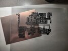
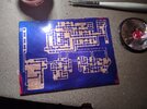
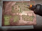
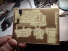
Slowly getting it done :)
 

Attachments

  • 1s.jpg
    1s.jpg
    2.6 MB · Views: 5
  • 2s.jpg
    2s.jpg
    1.8 MB · Views: 5
  • 3s.jpg
    3s.jpg
    1.8 MB · Views: 2
  • 4s.jpg
    4s.jpg
    1.3 MB · Views: 5
  • Like
Reactions: Handy Andy

dxChat
Help Users
  • No one is chatting at the moment.