I can honestly say that if ever a WWDX thread has really resonated with me, this is it!
Last edited:
After having read that, I'm glad my antenna doesn't suffer from low T!The shorter antenna designs - read this as less than 1/4 wavelength or like the 5K is shorter than a 102" whip - the "R" value changes - goes lower - when the antenna is shorter than it should be.
- - it then has to add length by using inductance (coil wind) to restore that "X" value
- - but it cannot compensate of bring the R-value back up to 50Ω
- - to make the SWR Impedance closer to 50Ω the XL is added
- - but adding that extra wire cannot bring back R except for being what the antenna "appears as" to the system - an antenna with a Lower R - which means it's offset by winds of wire to balance out Z to be closer to 50Ω
- Your R value even though the antenna is shorter - helps to reduce the needs of the antenna having to REQUIRE extra wire because it can't make up the difference in height "Big R versus Little R ". - which helps reduce the dependence of Z (Impedance) requiring XL and XC having to make up the difference (your Conjugate used by the antenna)
yup, ALOT of people like to turn simple things into the most complicated, math driven, physics expert gibberish. the bottom line of antenna design is simple, build the antenna for resonance at the operating frequency, then match feedpoint impedance to transmission line using the appropriate method. done! that is the correct way to build an efficient antenna system. periodI adjust my antenna to the lowest possible swr, from the radio using the installed coax and forget it.
Never had any problems and never fried a radio.
And, had several really good talkers. Both local and skip. All of the other stuff mentioned here is WAY too complicated for me. Anyway, I do it how I do it, no problems at all. Ever.
(even though I can't see his images)
Folks who tune for the lowest SWR are certainly doing the right thing if that is the only instrument you have, but for someone as serious as the OP, he's on the right track in optimizing his pattern for the effect that he wants.
Great, I saw your images.I've actually been experimenting with my tunes again recently (since covid). I took a spectrum analyzer (the kind that plugs into the computer) and stream the output online using twitch. I then use a laptop connected to a mobile internet connection to read that data on-site. This allows me to test a mobile tune in multiple locations in various directions. Long story short, what I have found is at least for local communications, it seems that the tune I described above using a second antenna attached to my nano-vna's second port as measured 100 feet away is confirmed for mobile measurements as tested from various locations and directions between 5 and 20 miles away from the shack.
Again, as I essentially posted above, this is just me being picky and pushing my knowledge. You won't notice the difference between this tune and tuning using SWR or resonance. There just isn't enough of a difference in output between said tunes to make any real difference...
The idea was inspired by an observation I made from a heated debate that has since been resolved between two other members of this forum, Marconi and Shockwave. I noticed after the fact that they were using two very different ways of measuring data to support their arguments. So thanks to both of you as various realizations from said debate from years ago are still bringing ideas to me, even if I'm not using the antenna in question...
The DB
I don't think those scenarios are going to be detectable outside of laboratory conditions & instruments.
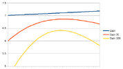
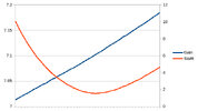
About your graphs though, the modeling software I've used, EZ-NEC & MMANA-GAL, don't consider source impedance or reactance in their gain calculations, so if you are modeling for a certain radiation pattern of an antenna at a given frequency, to actually get that calculated gain, you need to match the feed-point impedance of the antenna to the rest of your system, are you doing that?
(For people following along) In other words, if you want the 2.15 dBi theoretical gain of a 1/2λ dipole over an isotropic radiator, for a 50Ω system, in practice, you'll only get 2.15 dBi gain if your antenna feed-point impedance is also 50Ω; If you have an input impedance of 73Ω (which is what a dipole has in "free-space"), that would create a 1.46:1 SWR, and your gain would not be 2.15.
So I'm curious if that is taken into consideration in your graphs of Gain & SWR?


