• You can now help support WorldwideDX when you shop on Amazon at no additional cost to you! Simply follow this Shop on Amazon link first and a portion of any purchase is sent to WorldwideDX to help with site costs.
  • Click here to find out how to win free radios from Retevis!

Isn't she pretty

ShadowDelaware

Well-Known Member
Jun 20, 2023
176
132
53
45
South jersey, North Delaware
udxcbradio.com
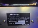
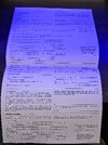
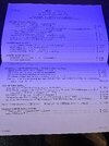
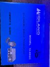
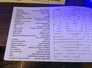
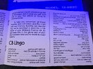
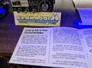
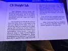
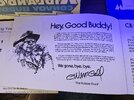
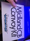
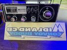
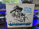
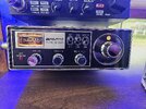
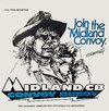
Brand new from August of 1976 Midland Model 13-882c. I dig the original decal and how the paperwork states "printed in Japan"
 

Attachments

  • 20240516_173623.jpg
    20240516_173623.jpg
    2.5 MB · Views: 34
  • 17158957726116995064103268295057.jpg
    17158957726116995064103268295057.jpg
    1.8 MB · Views: 27
  • 17158957525201709149714698850328.jpg
    17158957525201709149714698850328.jpg
    1.9 MB · Views: 20
  • 1715895733847614752491911687437.jpg
    1715895733847614752491911687437.jpg
    1.7 MB · Views: 19
  • 17158957140963161322741223966248.jpg
    17158957140963161322741223966248.jpg
    3.2 MB · Views: 17
  • 17158956989136733975535763468068.jpg
    17158956989136733975535763468068.jpg
    3.2 MB · Views: 20
  • 17158956780318970579373942904351.jpg
    17158956780318970579373942904351.jpg
    3.3 MB · Views: 21
  • 17158956598678885814464926503740.jpg
    17158956598678885814464926503740.jpg
    3 MB · Views: 21
  • 17158956433568532683474617021241.jpg
    17158956433568532683474617021241.jpg
    2.9 MB · Views: 22
  • 17158956288021921046356294946142.jpg
    17158956288021921046356294946142.jpg
    1.4 MB · Views: 29
  • 17158955327831144295630417813744.jpg
    17158955327831144295630417813744.jpg
    3.4 MB · Views: 32
  • 20240516_173555.jpg
    20240516_173555.jpg
    4.1 MB · Views: 39
  • 20240516_173609.jpg
    20240516_173609.jpg
    4.3 MB · Views: 36

That "Midland Convoy" picture on the box is just screaming 1976 at the top of it's lungs LOL! Enlarged it would make a great radio room poster...........

At first I thought you had put blue LED's in the radio, but it's just the way the photos are for some reason. Phew! I'm so NOT a fan of blue LED's.......bleccch !
 
I just need to find someone local.
Do it yourself ! That circuit with the PLL02A chip is a great one to learn on ! The conversion for uppers on that radio only involves a couple switches, a couple of diodes and resistors, and an ability to solder.

Only one small problem......... the 02A chip can give frequencies up into 28 MHz, but you've got an AM only radio there and above 26.355 is ALL sideband channels, so even though the radio will go there, it's not especially useful seeing as it's only AM!
You will however gain channels 24 to 35 so there's that. Unfortunately, the 02A circuit will not go below channel 1, so the AM freqs. below that can't be reached by that radio at all.......

You could get all those lower frequencies if you can find an old Expo kit for the 02A chip, which involves adding a couple mixer crystals.
That makes sense and now I understand why a few of the old 23 channel radios I looked at had only 12 extras above 23.
 
The 02A will give you lows all the way down to 26.645Mhz with no missing frequencies in 10Kc steps, provided that you also program the 10KC pin 15. No extra mixing crystals are needed. In my experience it will go down even lower, but radical re-tuning is required that would also affect the normal channels. The same goes for any mod to obtain all the regular 40 Ch frequencies. Programming all depends how the circuit board and channel selector access the PLL. There are different versions (two crystal and three crystal), but rest assured the 02A is totally capable. Your 13-882C is an early three crystal radio. There’s even a 5Kc pin available, but I never messed with that pin. Programing is all done by isolating some pins, cuts in various traces, and by adding a few resistors. Sacrificing one or two switches on the front panel, or adding a dedicated switch somewhere else. It's all part of the job and what each individual wants. I converted a number of these Midland 02A Cybernets. Not so much to obtain the normal 40, but for frequencies down to 26.805Mhz. I once knew a group that used 26.865Mhz. As chance would have it, that frequency landed on Ch19, so going between the two frequencies was controlled by a single switch. Those guys loved that feature in their mobile.
 
Back in the bad old days of 23-channel CB radios, it was common for a radio with poor alignment to have an internal feedback squeal on the transmit signal.

Reducing the drive level to the driver transistor would cause this, often because someone had tried to "tweak" the band pass filter that follows the transmitter's mixer circuit. Most radios used three slug-tuned resonant circuits in a string between the transmitter's mixer stage and the first low-level transmit amplifier stage.

Simply turning one of those three slugs too far from its resonant peak would initiate this squeal on the transmit audio. Peaking all three of them for a proper 3.5 to 4-Watt carrier would stop it.

Had an unpleasant experience installing the ubiquitous TIP120 variable-carrier circuit in a Johnson 250 23-channel base radio. It uses the same circuit board as the 123A mobile CB.

Long story short, we ended up boosting the size of more than one filter capacitor and setting the minimum carrier level to a Watt and a half, if memory serves. Even after that much effort it would squeal with the carrier around a Watt or less.

40-channel AM-only CB radios don't seem to have this bad habit. Never have figured out why.

That particular Midland radio might work just fine with a carrier control circuit added to the radio's driver transistor. Haven't tried that trick on that model.

Might work just fine, might not.

Back in the day we thought we were pretty clever, placing a 100uf electrolytic cap in parallel with R131, a 10-ohm resistor in series with the driver transistor's collector circuit. This would improve the radio's peak modulated power without changing the carrier level.

A typical TIP120 carrier control would go in place of R131. Seems to me I posted a schematic of the circuit we use, some time in the last 15 years or so. Not sure quite what search term would allow drilling down a search for that post.


73
 
That "Midland Convoy" picture on the box is just screaming 1976 at the top of it's lungs LOL! Enlarged it would make a great radio room poster...........

At first I thought you had put blue LED's in the radio, but it's just the way the photos are for some reason. Phew! I'm so NOT a fan of blue LED's.......bleccch !
That was the best C.W. McCall logo pic I’ve seen. I agree, that one needed to be saved and enhanced for future use as a poster or smaller accent in an old school shack. That logo was placed on a number of different Midland models during that time period. I decided to delete the reference to any particular model for that reason.
C.W. McCall logo.JPG
 

dxChat
Help Users
  • No one is chatting at the moment.
  • @ kopcicle:
    If you know you know. Anyone have Sam's current #? He hasn't been on since Oct 1st. Someone let him know I'm looking.
  • dxBot:
    535A has left the room.
  • @ AmericanEagle575:
    Just wanted to say Good Morning to all my Fellow WDX members out there!!!!!