• You can now help support WorldwideDX when you shop on Amazon at no additional cost to you! Simply follow this Shop on Amazon link first and a portion of any purchase is sent to WorldwideDX to help with site costs.
  • Click here to find out how to win free radios from Retevis!

low output from this 4 pill

Amp builders SHOULD all be incorporating low pass filters into their designs. It's cheap and irresponsible not to.
These are CB amps.
Adding anything to the cost to clean up the IMD or harmonics is not the case.
I know you come from a commercial radio background but it's been this way since the early days of CB radio.
Many of the early comp style CB amps did not even have negative feedback and when the buyer complained about the amp staying keyed they told them to keep changing jumpers untill it did.
It is what it is.
Extra parts add cost that cuts into profits.
That is the bottom line.

73
Jeff
 
It would also severely impact their wattage claims, losing them sales. If seller A sold a similar amp to seller B but seller Bs cost more due to the added filtering, but quoted a lower (more realistic) output figures most of the CB community would abandon builder B for builder A and their ghost watts. As Shockwav said, just the way it is. I was guilty of that thinking many years ago myself.
 
Last edited:
  • Like
Reactions: BC Coyote
You nailed it there AudioShokwav & Lonestar ! Anything that makes even a tiny dent in wattage claims gets eliminated. As does every "unnesscessary" part, in order to save money.
I've owned lots of CB amps over the years. When I started out I just ran them stock, but after complaints of crunchy audio from fellow operators and complaints from my girlfriend at the time of the TV being wiped out when I transmitted, I learned how to bias them properly for sideband and started using LPF's.
I still own a re-biased and filtered Palomar 200. It sounds fantastic, and I still get over 160 watts peak from it. I occasionally hook it up to an old 148GTL side mic and make some contacts when I get on a "retro" kick !
 
Once you float those 3 things you should be fine and thats why the output is low.
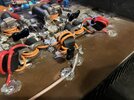
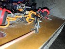
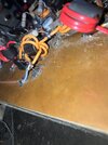
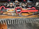
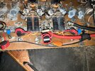
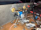
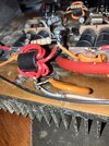
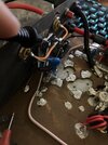
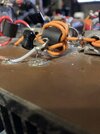
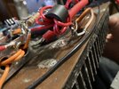
How about a better pic of the output side at the giant round ceramic capacitor.
IMG_3562.jpegIMG_3563.jpegIMG_3564.jpegIMG_3565.jpegIMG_3566.jpegIMG_3567.jpegIMG_3568.jpegIMG_3570.jpegIMG_3571.jpeg
IMG_3562.jpeg
IMG_3563.jpeg
IMG_3564.jpeg
IMG_3565.jpeg
IMG_3566.jpeg
IMG_3567.jpeg
IMG_3568.jpeg
IMG_3570.jpeg
IMG_3571.jpeg

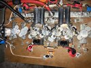
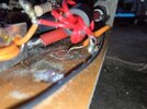
Here are some better pictures, so for the time being I’m not really worried about the low pass filter as it’s not a necessity and it’s not why the amp isn’t working.
 
Ok.back to the point. Is the coax shorted? Did you move the wire and rekey? Does the relay click when u key the box? 5 pages of debate about transistors and lowpass filters and YouTube, jesus guys ...
Help the guy fix his box, not lecture him.
the amp will click and dead key 50w, I am not sure what wire you are referring to.
as far as my coax ran to my antenna it tested good with a multimeter, A few of my coax jumpers are a little squirrely in terms of the pl259 connectors being touchy in the sockets. sometimes I have to turn one just slightly to get it to make a proper connection
 
Well, I don’t think this is supposed to have a Continuity black probe on the center of coax going to relay, red probe on the copper plate, if I understand correctly, the copper plate is ground? And power comes off that BUS rail? also, the closest pl259 socket is labeled radio, but earlier someone said that was the output side of the circuit. Did I drive it backward because the sticker on the back is wrong?
 

Attachments

  • image.jpg
    image.jpg
    1.7 MB · Views: 74
Thanks for posting better pics.
I don't know if you soldered anything or not yet.
In you last probe pic it will have continuity if either of the 2 coax cables running from the relay to the amp combiners...thats the coax on the orange wire wrapped one originally in question and the red wire wrapped one on the opposite side with large orange cap touch that copper plate. Thats what you need to make sure of first.
 
No, and yes. It appears the center conductor is soldered to the copper board inside the blue circle, same copper board that the coax shield is soldered to outside the circle. They both appear to be soldered to the same copper plane. Could be the pic but it looks like a short.
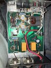
I’m getting my replies a little bit mixed up because I’m doing this on my phone, but cable guy I sent in better pictures of that section you circled it does appear to be floating, now I tested continuity between the center of the coax where is soldered to the relay and the copper plate, and I have .3 ohms of resistance. I should have an open loop, correct? Also picture of my two pill because somebody asked for it.
 

Attachments

  • image.jpg
    image.jpg
    3.2 MB · Views: 77
I asked for the pics :)
There will be some measurement, its part of a circuit.
Make sure the other side floats too on the output. Its dangerously close to the copper board. Try to lift it away.
 
I asked for the pics :)
There will be some measurement. Don't forget the caps on each end of the coax on the copper board. Make sure the other side floats too on the output. Its dangerously close to the copper board
So if I understood your last reply correctly, I tested for continuity on both the original side in question and the side with the large button cap and everything seems to be making good connection in those 2 areas, while doing that I checked the ohm reading on some of the resistors the gray resistors going over the pill sections have 99.9 ohms of resistance which I think is correct, however on the brown resistors the ones that wire into the combiners I’m only we getting .3 ohms, now this could be because of the way it soldered into the combiner I assume, now what I don’t understand what you’re talking about that’s dangerously close, is it to solder joint from the center of the coax to that cap and combiner? are you talking about the leg of the capacitor that soldered to the copper plate?

edit; I see what your talking about its on the output side where the coax gets solderd to the button cap
 

Attachments

  • image.jpg
    image.jpg
    1.6 MB · Views: 66
  • image.jpg
    image.jpg
    2.4 MB · Views: 65
Last edited:
.the 99.9 ohm(100 ohm) resistors are good. it looked like they had red stripes but apparently they were brown on the large feedback resistors. The possible trouble areas that were discussed were not touching the copper ground plane, thats good.
Now we delve deeper.
 
Last edited:
Well, I don’t think this is supposed to have a Continuity black probe on the center of coax going to relay, red probe on the copper plate
That would show continuity at DC as the input is grounded (from a DC perspective) via the orange input transformer winding to ground. The RF sees the transformer, the DC continuity meter only sees the resistance of the winding.
 
.the 99.9 ohm(100 ohm) resistors are good. it looked like they had red stripes but apparently they were brown on the large feedback resistors. The possible trouble areas that were discussed were not touching the copper ground plane, thats good.
Now we delve deeper.
so from here, my next step would be to test the caps on the transformers? i don't know where I can get a pf tester locally but I'll order one. if those joints are good and the coax connections and resistors are good. The only other major components that could factor into this problem would be the caps or the pills? I do see there are metal clads on the big transformers instead of caps.
 

dxChat
Help Users
  • No one is chatting at the moment.
  • @ kingmudduck:
    Hello to all I have a cobra 138xlr, Looking for the number display for it. try a 4233 and it did not work
  • @ kopcicle:
    If you know you know. Anyone have Sam's current #? He hasn't been on since Oct 1st. Someone let him know I'm looking.