• You can now help support WorldwideDX when you shop on Amazon at no additional cost to you! Simply follow this Shop on Amazon link first and a portion of any purchase is sent to WorldwideDX to help with site costs.
  • Click here to find out how to win free radios from Retevis!

MC145106P info needed

Im here in Boston Ma. So I tried everything to log in and nothing. Oh well I think they are blocking USA IP addresses so you cant log in but can only view the forum.

Merry Xmas to all
Hi Techno I have no problem using my US vpn that is private and have static ip

Actually I used for all the streaming services available for the US market like Youtube TV ,DAZN ,ESPN ,Paramount,
Directv Stream,etc.

Merry Xmas :)
 
Attached are the datasheets for the MC145106p and the MB8719. Take a look at the truth tables.

You will see something strange with the MB8719 in that a 0 on the most significant bit (P6) acts like a 1 on an imaginary 8th input (if it had a P7) and that changing it from a 0 to a 1 makes the count start at 64 rather than 128. The MB8719 does have a P7 internally, but it is not accessible from the outside. It is driven by an inverter connected to P6.. Note that in the Uniden Washington, this pin is soldered directly to ground ensuring the count starts at 128 all the time, and that the radio only uses P0-P5. If P6 was low and it actually treated it as 0 instead of providing a high on an internal P7 and you started increasing the least significant bits, the divider would start dividing by 1,2,3 etc., but it can't because that inverted signal to P7. Being it only has a total of 7 inputs, P0 through P6 (and P6 is always low providing a high on that internal P7), you can get divide by N's with N ranging from 128 to 192 as is in the radio, and 64 to 128 by lifting pin 10 (which opens up 26.215 to 26.845).

Going to the truth table for the MC145106P, we see that it has a P7 and a P8, so there is no need to interpret a low on P6 as a high on P7. This means that for this PLL to act like the MB8719, you simply need to pull P7 high to cause the other inputs to start counting at 128. The other difference is that this PLL has a pin (MC145106p pin 6) that changes the step from 10kc (pin high) to 5kc (pin low) if using the usual 10.24MHz reference crystal. Over all, this PLL will divide by n=2 to n=511.

I hope that gets the wheels turning :)
Edit: just don't forget what Dr Frankenstein said about the VCO range and bandwidth issues. You might be able to tell the PLL what to do, but it still requires the rest of the radio to cooperate.
 

Attachments

  • MB8719_ETC.pdf
    252.3 KB · Views: 10
  • MC145106.PDF
    124.5 KB · Views: 12
Last edited:
Techno1,

There are really only two kits like this in existence right now, and one of those is the digimax kit.

It may be a bit expensive but you'll find it's worth it because these kits have been around for a a long time and come with pretty good install instructions.

that said, doing channel mods to a radio is never a 'plug and play' situation as there are always things to re-tune, and there are always chances to ruin the radio while installing the new kit.

many a radio has been put on a shelf permanently because the ad said the kit was easy to install.

ive installed quite a few of these kits and i wouldn't recommend anyone try it who doesn't already work on electronics because once you are done and it doesn't work you are going to be completely lost on how to get it working and will be on your own because no shop is going to want to try to fix your work.

better to just have a shop do the install/modifications for you in the first place.

the kit in your picture comes from here i think:

this is from Germany i think and i've never installed one of his kits.

hope this helps!
LC
 
  • Like
Reactions: tecnicoloco
I did the binary stuff in excel. For the Uniden Washington with the 11.125MHz tripler mixing with the VCO in the loop and 7.8MHz at the tx mixer, this is what to expect.

Altering the binary data of the MB8719, you can go from 26.215 to 27.485. To do so will require a VCO range of 34.015 to 35.285.

With the MC145106P, you can get 25.585 to 30.685. This will require a VCO tuning range of 33.385 to 38.485. To get all of that range will require a lot more work ~ unless you are happy with it falling out of lock, the BW issues, and accepting what range works as is..

The crystal swapping method does the same thing to the VCO frequency range because as that mixes with the VCO in the loop mixer, the VCO needs to change by the same amount to achieve phase lock. You will have no issue getting the triple nickel by swapping PLL's, but if you expect to run at the top of 10m or down on 12m, it might throw a fit without further work.

Although not necessary, I would suggest a micro for the binary because a few of the 10kc frequency steps are skipped in the 11m band, like 27.195, and how ch23 is higher in freq than ch24 and ch25. This lets us know that the rotary encoder is not in perfect binary sequence. So just remember that one click of the dial does not always shift the radio in 10kc steps, and that makes the freeband frequencies a mystery without a chart when using the factory encoder dial. Ch 1-40 will be fine using the same dial after the swap as long as you pull P7 of the MC145106P high, just be aware of the sequencing of it outside the band.

I made a spreadsheet relating the binary inputs to the expected frequencies for both the MB8719 and MC145106P for anyone wants to Arduino a PLL with a fun looking ch display (sorry digimax). If the radio has a different set of IF's compared to the washington, those can be changed in the spreadsheet to recalculate the binary inputs vs frequency table.
 

Attachments

  • PLL Binary for MB8719 and MC145106P.xlsx
    102.4 KB · Views: 13
Good stuff Brandon!

the broadbanding is a diminishing return thing.

once you broadband the receiver enough to cover even most of that range, you've ruined pretty much all of the selectivity the radio has, and the receiver is one of the best parts of an MB8719 chassis.
LC
 
Techno1,

There are really only two kits like this in existence right now, and one of those is the digimax kit.

It may be a bit expensive but you'll find it's worth it because these kits have been around for a a long time and come with pretty good install instructions.

that said, doing channel mods to a radio is never a 'plug and play' situation as there are always things to re-tune, and there are always chances to ruin the radio while installing the new kit.

many a radio has been put on a shelf permanently because the ad said the kit was easy to install.

ive installed quite a few of these kits and i wouldn't recommend anyone try it who doesn't already work on electronics because once you are done and it doesn't work you are going to be completely lost on how to get it working and will be on your own because no shop is going to want to try to fix your work.

better to just have a shop do the install/modifications for you in the first place.

the kit in your picture comes from here i think:

this is from Germany i think and i've never installed one of his kits.

hope this helps!
LC
He LC

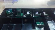
A few of the modules from Ing Maurer
 

Attachments

  • Modulos PLL 858-PLL 861-MB 8719-PLL 2816-PLL 03A.jpg
    Modulos PLL 858-PLL 861-MB 8719-PLL 2816-PLL 03A.jpg
    2.2 MB · Views: 15
Thank you all for the info and help and suggestions just something im toying with at this time. I do have some info and a kit on the way will be about 3 weeks delivery and then to install in radio. See what happens.
 
Thank you all for the info and help and suggestions just something im toying with at this time. I do have some info and a kit on the way will be about 3 weeks delivery and then to install in radio. See what happens.

so you went with the digimax kit eh?

as i said its a good kit and does work when installed correctly.
be careful of static when working on things like this.
for example, working on a carpeted floor is a bad idea.

do you have the test equipment and experience required to re-align the radio once you are done?
because you are going to have to.
LC
 
I finally received the channel kit with easy directions and how to broadband the vco.
Remove the 8719/8734 and add a socket. Then this kit plugs into the socket.

Comes with a 5 position rotary sw that has a couple of diodes on it.

no ground no power wires just plug in

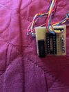
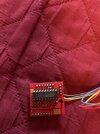
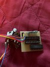
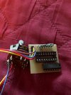
In the pictures would anyone know what might be the 14 pin chip on the kit.
Im sure they are using the mc145106p pll but need the info on the 14 pin chip.
Also you can see some resistors and there is 1 jumper on the board.

So i will try the kit tonight and see what happens on a Washington since its all set with a pll socket
 

Attachments

  • thumbnail_IMG_8230.jpg
    thumbnail_IMG_8230.jpg
    100.8 KB · Views: 20
  • thumbnail_IMG_8231.jpg
    thumbnail_IMG_8231.jpg
    113.2 KB · Views: 23
  • thumbnail_IMG_8232.jpg
    thumbnail_IMG_8232.jpg
    84.3 KB · Views: 19
Maybe I should have bumped the old thread talking about this, but it seemed worth mentioning here as you are about to mod a radio that may have more tricks up its sleeve as is.

That thread talked about the MB8719 and how some of them (the original Fujitsu's, not the RCI8719s) can get around that internal inverter controlling P7 and have both P6 and P7 high. This is supposedly accomplished by setting the voltage on P6 somewhere between high and low.

If I had to guess why this works, I would say that the divider inputs have a lower turn-on voltage than the inverter input does and that allows you to push P6 into the high state while the inverter input stays low (keeping P7 high too). It is just a matter of finding the sweet spot.

Edit: If that works on your 8719 (supposedly not all 8719's are this cool), it would give you the missing uppers.
 
Last edited:
  • Like
Reactions: NZ8N
So I tried the kit and it works pretty good. I was able to get to 28.535 and down to 26.515 with power enough to transmit. You need a freq counter to know where you are. It did go to 29.325 if I tuned the radio for that high but retuned back to 28.535 - 26.515. Also had to add a toggle to jump pins 11 and 12 on the pc board to get 26 815-26.955 and also ch 41 - 55 in the high band location.

So would anyone know what might be the 14 pin chip used in the pictures I posted
 
Kit is working pretty good.
I know for sure the 18 pin is the MC145106P pll.

Im still looking on what might be the 14 pin chip use on this kit. here is picture.
Any suggestions/Ideas
 

Attachments

  • thumbnail_IMG_8232.jpg
    thumbnail_IMG_8232.jpg
    84.3 KB · Views: 6

dxChat
Help Users
  • No one is chatting at the moment.