• You can now help support WorldwideDX when you shop on Amazon at no additional cost to you! Simply follow this Shop on Amazon link first and a portion of any purchase is sent to WorldwideDX to help with site costs.
  • Click here to find out how to win free radios from Retevis!

Modeling mobile antenna in EZNEC

Blue_Max

Member
Jun 1, 2011
7
0
11
Bavaria
Hello to all,

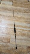
I tried to model this mobile antenna https://www.wimo.com/en/62006 with the 1123 antenna base in EZNEC, shortened according this table to 404MHz.
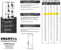
Screenshot 2024-11-06 084627.png20241106_064741.jpg

It is designed to be a colinear stacked 1/4λ+1/2λ antenna. My focus was to model the geometry as exact as possible.
But I have two questions:

1. As I have modeled the helix quite exact, will EZNEC then automatically calculate the inductivity / capacity in its modeling? The value for the helix would be 0.519µH and 1.168pF.

2. How can I model a car roof in EZNEC?

Some more background information: I want to use this antenna for DAB+ reception (174-230MHz) and want to know how it behaves as a colinear stacked 1/8λ+1/4λ antenna for 202MHz.

Some help / advice is appreciated. Thanks in advance.

Best regards
Oliver
 

Attachments

  • stacked_colinear_mobile_ant.txt
    26.5 KB · Views: 27

1. As I have modeled the helix quite exact, will EZNEC then automatically calculate the inductivity / capacity in its modeling? The value for the helix would be 0.519µH and 1.168pF.

I model primarily in 4nec2, but both EZnec and 4nec2 use the same nec2 engine.

When modeling a coil, the software will make adjustments on inductance and capacitance within that coil, but most people use small straight lines, and because of that, what the software calculates will be off to some degree.

In 4nec2 it allows me to, instead of a wire, use an arc, and a helix. I'm not to familiar with these features as most of what I modeled didn't require their use. I would see if they are available options in EZnec and see if you can find info on them. One or both of these should get you closer to being accurate.

Another option, in 4nec2, I can add a lump sum of inductance and capacitance to a segment on the antenna. As you know this data already you could see if EZnec will allow you to do the same.

2. How can I model a car roof in EZNEC?

When I modeled vehicles in the past, I created wire frameworks for the entire vehicle. However, this was for HF antennas. I learned a lot of interesting things about how antennas actually function on vehicles, and were currents actually flow. I can't speak to anything higher than 10 meters. You might try a wire grid in the dimensions of said vehicle roof. For 10 meters (27 MHz) I would use 1 foot grid squares, but I would make them much smaller for the frequency you plan to use.

If your just looking to see if that antenna has a collinear effect, you don't need to model the vehicle, you can model the antenna over a ground plane. Yes, there will be differences to a real world patterns, but if you just want to confirm the collinear effect that is enough.

In my experience, actually modeling vehicles gets to be very tricky when it comes to modeling. They require the use of a lot of segments as well. You can, with work, get very accurate models with them, but its going to take a lot of time and experimentation. The latest models I made for vehicles factored in some of the curves as no modern vehicle (except jeep wranglers and gladiators apparently) use flat panels anywhere. These curves are enough to change the radiation pattern for the HF antennas I tested.

A note from experience. If you want to model mobile antennas on vehicles, and you want accuracy, expect to go way down that rabbit hole over time making lots of adjustments and improvements.


The DB
 
Hello DB,

thank you for your answer.
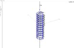
Basically EZNEC has a helix function, otherwise it would be nearly impossible to create it. And this works quite well.
Helix.JPG

Regarding the roof, I think to see how the antenna performes around 202MHz a groundplane is more than sufficient, I agree with you. But how can I define this?
What I don't also understand is, why I can't create a source at the bottom of my antenna? I can't go lower than segment 2.
source.JPG

I attached a ziped EZ-model of the antenna.

Best regards
Oliver
 

Attachments

  • stacked_mobile_antenna.zip
    2.1 KB · Views: 29
Regarding the roof, I think to see how the antenna performes around 202MHz a groundplane is more than sufficient, I agree with you. But how can I define this?

I would start with four 1/4 wavelength radials at the height of the vehicle's roof. Easy to make and typically very effective.

What I don't also understand is, why I can't create a source at the bottom of my antenna? I can't go lower than segment 2.

Looking at the model, when it comes to a segment at the end of the wire and placing a source there, make sure the end of the wire is connected to other wires. If it isn't then the nec2 software will throw up an error message so most interfaces like EZnec and 4nec2 detect it and error out before it happens. The groundplane mentioned above is a good option. Basically, log story short, even on end fed designs, there must always be something (even if it is only one segment of wire) attached to both ends of the feed point.


The DB
 

dxChat
Help Users
  • No one is chatting at the moment.
  • dxBot:
    Greg T has left the room.
  • @ BJ radionut:
    EVAN/Crawdad :love: ...runna pile-up on 6m SSB(y) W4AXW in the air
    +1
  • @ Crawdad:
    One of the few times my tiny station gets heard on 6m!:D
  • @ Galanary:
    anyone out here familiar with the Icom IC-7300 mods