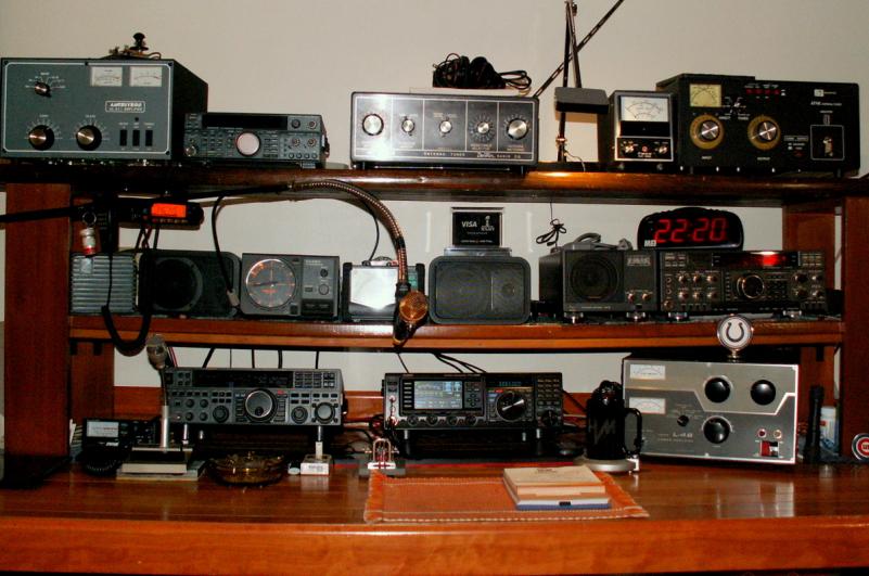
You surely need a bench topper now with the extra gear!!!
See mine:

Old pic...bench still the same...but equipment has changed some.
See mine:

Old pic...bench still the same...but equipment has changed some.

It's nice to see that now the more interesting part of the construction is running. Arranging the power supplies is almost always a question of space, as they usually end up somewhere in the lower part of the shack.Should be able to lay out nicely the rigs and power supplies. I like the supplies on bottom away from the rigs if possible to cut the RF if any.
That LMR is some nice cable, I run the 400 myself. I get them to put the ends on for me because it is such a critical part of the system, I don't want to take a chance. The LMR flex is good too and I have 10 foot 400 flex jumpers for the amps and the line into the shack. I am also going to use a 10 foot flex to wind an air choke at the antenna feed point. Your station is coming together nicely and you will no doubt enjoy it for years to come.
That LMR is some nice cable, I run the 400 myself. I get them to put the ends on for me because it is such a critical part of the system, I don't want to take a chance. The LMR flex is good too and I have 10 foot 400 flex jumpers for the amps and the line into the shack. I am also going to use a 10 foot flex to wind an air choke at the antenna feed point. Your station is coming together nicely and you will no doubt enjoy it for years to come.
Chris
Wow thanks LC. So it goes at the amp output? I run different amps off of the same antenna, could I just put it on the coax where it leaves the shack? I am going to check this out right now. Sorry for the hijack OP,I will start a different thread for this.ShadeTree Mechanic, save yourself the trouble and inconvenience of winding that common mode choke.
get some ferrite to put around the coax at the feedpoint instead.
It is much easier to do, and it works better than the air wound choke.
the whole reason air wound chokes became popular was because of a misconception of a very famous chart that we have all seen online that shows the various turns and diameters of air chokes for different frequencies.
(its the one with all the red green and yellow on it)
the guy who made it only did so in order to show how much better ferrite worked, but only one of his charts made its way around the interwebs, so everyone treats it like a set of instructions for getting rid of common mode currents. It's true purpose was to show that this was not the ideal way to do that.
do yourself a favor and buy one of these kits, or order the same ferrite beads directly from Amidon and save some money.
https://www.ebay.com/itm/Palomar-Engineers-Slip-On-Coax-Feed-Line-Choke-1-2-12-7mm-cable-1-8-300-MHz/192448617551?hash=item2cced4dc4f:m:mg7hwEr-TOFhBJxRfX-mNtw&var=492461290816&_sacat=0&_nkw=palomar+engineers&_from=R40&rt=nc&_trksid=p2057872.m570.l1313.TR1.TRC0.A0.H0.Xpalomar+engineers.TRS0
If you had an extreme case of common mode currents at your station, you could run two of these kits at the feedpoint, but one should really be enough for most CB antenna situations.
LC
