On my next attempt, I am going to use a non-mosfet dx-949 and compare osc levels, from the PLL, VCO, BM and mixer on my service monitor/spectrum analyzer. Something isn't right with the low level signal. I see a spur way too high in amplitude, way too close to the intended frequency. Unfortunately, I don't have any parts like the AN612 or S042P around. I would have to rob from a working radio, which I am hesitant to do.When you see Siemens - then you get predictable Results.
When you see RCI in the Chips' ID - stamp - run the other way...
Thats why I posted the "???".
Wildly varying quality from RCI - you can almost guess the year it was made by just the quirks it had during operation.
Pretty much what you had to do is look at the schematic,
Thinking...
- ok, I see 5 gets power, so 2 and 3 will be close in DC values
- - Pin 11 and 12 - Do I care? Or Should I care? They Feed each other and match impedance output to input thru that broadbanded Resistor
- - so you'll see AC there all the time (If L44 and L43 are sending signal to be mixed...)
- 9 and 6 SHIELD 7 and 8 - 11 and 13 with 14 (6, 9 and 14 Signal GND to cans) have signal float DC level at 1/3rd to 1/4th of input DC voltage
- - e.g. - have sine wave but bias is present and is pulled down even greater (to lower DC Bias voltages) when the loading of the coupling coil to those pins is correctly "ringing"
- - hence both doorbells - front and back (PLL and VCO/Clarifier) are loading the chip with full bias current so DC is pulled down when fully working
- - the higher the DC float voltages on Signal pins - the less signal it is using.
-
You can now help support WorldwideDX when you shop on Amazon at no additional cost to you! Simply follow this Shop on Amazon link first and a portion of any purchase is sent to WorldwideDX to help with site costs.
-
The Feb 2025 Radioddity Giveaway Results are In! Click Here to see who won!
Need Help Galaxy DX-2547 Factory MOSFET No RF Out
- Thread starter SuperLid
- Start date
Perhaps looking at it from a working radio perspective,...
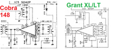
Might want to look at an older Grant XL or Cobra 148 - they use the S042P
Now why bring up an older unit - the pinouts.
Layouts too...
We had a discussion or two about the Siemens chip used when they have a dropping resistor on Pins 10 to 12 - while one radio uses one concept - another uses a different concept.
The part I'm talking about is you may have TOO much signal on one, while not enough on the other - slamming the mixer hard, and generating a square wave but not in the region of RF that you want it to be in.
Last edited:
I appreciate the suggestions. I am going to stick with the plan and look at the old DX-949 levels. Hopefully, I come up with something, or the hammer fix may be coming!Perhaps looknig at it from a working radio perspective,...
Might want to look at an older Grant XL or Cobra 148 - they use the S042P
Now why bring up an older unit - the pinouts.
Layouts too...
We had a discussion or two about the Siemens chip used when they have a dropping resistor on Pins 10 to 12 - while one radio uses one concept - another uses a different concept.
The part I'm talking about is you may have TOO much signal on one, while not enough on the other - slamming the mixer hard, and generating a square wave but not in the region of RF that you want it to be in.
View attachment 61139
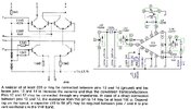
Sometimes the only way you can solve for X is to substitute values
and see it on a Scope in order to find answers as to which way the wind blows.
View attachment 61140
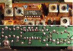
Even TDA had it's volley in the mix...
View attachment 61141
Problem found. Junction of IC6 pin 6/C144/R169, copper trace cracked around + lead C144 from pin 6. There were at least three of these same type of cracks around component leads. The PCB copper is too thin. This may be the worst quality PCB I have ever encountered in a radio. Even the old Galaxy is not this bad. Clearly, they have done cost cutting.
The TX is dirty as hell. I will go through the TX alignment and go from there, another day. I have said it before and will say it again. Friends, don't let friends, buy Ranger built radios.
The TX is dirty as hell. I will go through the TX alignment and go from there, another day. I have said it before and will say it again. Friends, don't let friends, buy Ranger built radios.
Last edited:
Those 69 series boards are the absolute thinnest, too much heat and foil lifts right off and in your case even cracks on its own.Problem found. Junction of IC6 pin 6/C144/R169, copper trace cracked around + lead C144 from pin 6. There were at least three of these same type of cracks around component leads. The PCB copper is too thin. This may be the worst quality PCB I have ever encountered in a radio. Even the old Galaxy is not this bad. Clearly, they have done cost cutting.
The TX is dirty as hell. I will go through the TX alignment and go from there, another day. I have said it before and will say it again. Friends, don't let friends, buy Ranger built radios.
Cost cutting rears it's head.
This radio took a hit on the left front. Had to straighten out the chassis and some of the controls were off center. I am not surprised there were cracks in the PCB, being that it is so thin. Had this been an older radio, it would have been a non-issue. The chassis is pliable with my hands/fingers. RCI=Really Cheap ImitationThose 69 series boards are the absolute thinnest, too much heat and foil lifts right off and in your case even cracks on its own.
Cost cutting rears it's head.
This radio took a hit on the left front. Had to straighten out the chassis and some of the controls were off center. I am not surprised there were cracks in the PCB, being that it is so thin. Had this been an older radio, it would have been a non-issue. The chassis is pliable with my hands/fingers. RCI=Really Cheap Imitation
R= really
C= cheap
I= imitation
I thought it was appropriate, because if you look at the circuits, they ripped them off from Uniden and did a really bad job of it, because they don't work right. The RX AGC in this POS is a complete ripoff of a Uniden, but still sucks. Must be *R*eally *C*heap *I*mitation parts!that's one to remember!
R= really
C= cheap
I= imitation
dxChat
- No one is chatting at the moment.
-
-
@ Geoexplorer69:Coax question. I just put up a new Sirio monsoon base antenna with 100’ of rg8u coax testing with myMFJ antenna analyzer shows 1.4 swr at 26.965mhz and a 1.1 at 27.405 mhz . When I checked the ohms it’s steady a 30 ohms across the entire bandwidth.
-
-
-


