• You can now help support WorldwideDX when you shop on Amazon at no additional cost to you! Simply follow this Shop on Amazon link first and a portion of any purchase is sent to WorldwideDX to help with site costs.
  • Click here to find out how to win free radios from Retevis!

Need help with a President Grant (Export model)

Summertown

New Member
Apr 29, 2023
8
5
3
60
Hi everyone!

(Hope this is the right place to post this ;-)

I got hold of a President Grant - Export model, chassis PC-999AD, in very good state.
I completed the whole alignment following the service manual at this link (the schematic is the one at p 26).

All is fine with the radio - with one exception: the RF power is not where it should be.
This kit is rated for 10W AM/FM and 21W for SSB PEP but all I get is 5.3W in AM (unmodulated) and about 9W PEP in SSB.

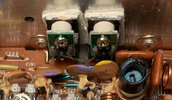
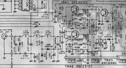
I started tracing the problem from the finals. This radio uses two final transistors in parallel (TR41 and TR42) to produce double the normal RF power output. Both are identical amplifier circuits driven by the same single driver, TR43.
finals.jpg

In the alignment, I set the bias of the driver (TR43) at 100mA; for the finals I set the bias at 50mA following advice I saw on some forums (the service manual suggest only 25mA).

I checked the DC bias voltages for the 2 finals and the driver in AM Tx mode unmodulated, and they are all reasonable.
I then measured the signal amplitudes: the driver (TR43) gives 17V p-p on the collector, as it should according to the manual.

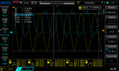
The two finals get about 12V p-p amplitude on the base but on the collectors I see only 20V to 22V p-p, whereas it should about 40V p-p according to the manual. Accordingly, in antenna on the dummy load I measure only 47V p-p, corresponding to 5.5W

Here are the signals on the bases of the finals (left) and on the collectors (right) (Tx AM unmodulated).

TR41 and 42.jpg

Here is another picture showing the collector voltage on one of the finals (blue) and on the antenna (yellow).
DS1Z_QuickPrint1 (2).png

My suspicion is that only one of the finals is working, hence half the power.

Any suggestion on how to verify this without unsoldering the TR41 and TR42 transistors?
Any other suggestions about other possible causes?

Many thanks in advance for your help!
 

If the bias is adjusting OK for each final, they are probably good. I suspect one of the shunt capacitors in the output tank has changed value. Check the values of C177, C183 and C184
 
  • Like
Reactions: Summertown and NZ8N
If the bias is adjusting OK for each final, they are probably good. I suspect one of the shunt capacitors in the output tank has changed value. Check the values of C177, C183 and C184
Many thanks for the advice!

I removed the caps, tested them for leak at 100V DC and checked the values.
C183 (nominal: 560pF) reads 600pF
C184 (nominal: 47pF) reads 74pF (in fact the cap installed was 68pF)
C177 (nominal: 150pF) reads 155pF

So I guess the next step would be (1) to put back C177 and (2) replace C183 and C184 (which are in parallel) with the correct capacitance. I could maybe determine the optimum capacitance by connecting a variable capacitor and adjust for maximum voltage amplitude on the load?
 
You might check C176 (It's hard to read, it's the 68pf closest to the antenna jack in the schematic). That cap hardly ever changes value but anything is possible. Also check the collector load C186, 150pf.
Instead if trying a variable cap, replace C183 first and leave C184 out, then add back C184 and see if the watts are better or worse.

edit: @SuperLid made me think, are you sure the ALC isn't set too aggressively?
 
Last edited:
  • Like
Reactions: Summertown
You might check C176 (It's hard to read, it's the 68pf closest to the antenna jack in the schematic). That cap hardly ever changes value but anything is possible. Also check the collector load C186, 150pf.
Instead if trying a variable cap, replace C183 first and leave C184 out, then add back C184 and see if the watts are better or worse.

edit: @SuperLid made me think, are you sure the ALC isn't set too aggressively?
I removed and measured C176 and C186, they are good (reading 70p and 151p respectively).
I put back C177 and C183 but not C184; but there is no improvement - still only 46.5V p-p on the dummy load (Tx AM unmodulated). It reaches 52.5V p-p with VR13 (AM Carrier power) all the way up, corresponding to 6.9W.

ALC is basically disabled, I have turned VR12 all the way clockwise for max output in SSB. VLC is not supposed to be active in AM Tx.

Should I test the finals by disconnecting TR41 (or just unsoldering the base) then put it back and disconnect TR42?

(edit) incidentally - isn't it odd that the signals on the collectors of TR41 and TR42 are slightly different (picture in my first post)? they are wired together ...

finals B.jpg
 
Last edited:
What are you using for a wattmeter?
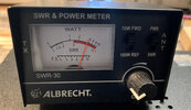
I do not have a very accurate Wattmeter for 27MHz, I only have an Albrecht SWR-30.
So I am measuring the amplitude of the voltage Vpp on the 50ohm dummy load with the oscilloscope, 10x probe, then I calculate
Power= [(Vpp/2)*0.7071]^2/50

With 52.5V p-p on the dummy, corresponding to 6.9W calculated, the SWR-30 reads this:

Power meter.jpg
 
Last edited:
If you want to run the finals one at a time you can leave them mounted but disconnect both the base and collector on the transistor you are temporarily bypassing.
 
  • Like
Reactions: Summertown
A somewhat riskier but faster approach is to take a pair of hemostats and short across base to emitter of first one, then the other final transistor. If both are contributing equally to the output power you'll see the same drop in power either way. Even if one final transistor is totally dead you'll see a drop in power shorting the input of the dead transistor. But if one of them is really not working you'll see the power drop to zero when the good transistor gets the drive removed from it this way.

And if you see more or less the same drop in power doing this to each final, they're both working.

Takes a steady hand. If you accidentally bridge the base to the collector, it won't matter how quickly you draw the tool away. This will surely croak a good final if it happens.

73
 
I did not have the stomach for doing it with the hemostats:sneaky: so I did the test with the base and collectors disconnected.

With only TR41 disconnected the voltage on the dummy load measures 36V p-p
With only TR42 disconnected the voltage on the dummy load drops to 2V p-p!
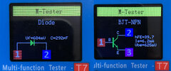
Testing the two finals with the multi-meter gives (TR41 left)

Tester.jpg

So I am shopping for a pair of 2SC2312. I can get get some new on Ebay.
Alternatively - are there better alternatives to consider for these finals?

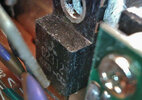
2SC2312C.jpg
 
  • Like
Reactions: Holydvr
It's very rare for a bipolar final to be "bad" yet still have the bias set normally (I think it's only happened to me once in 40+ years), that's why I pointed you towards the tank caps as they change value all the time. (there were a couple a little off)
As far as replacements, finding real ones is a crapshoot and not recommended. The ones on eBay are fake %99 of the time. I have had good luck with the HG-2SC1969's working well but never tried their HG-2SC2312 offering.
I apologize for the extra work. :(
 
Last edited:
It's very rare for a bipolar final to be "bad" yet still have the bias set normally (I think it's only happened to me once in 40+ years), that's why I pointed you towards the tank caps as they change value all the time. (there were a couple a little off)
As far as replacements, finding real ones is a crapshoot and not recommended. The ones on eBay are fake %99 of the time. I have had good luck with the HG-2SC1969's working well but never tried their HG-2SC2312 offering.
I apologize for the extra work. :(
Not at all! It was little work and the right thing to do to check the output tank circuit first. Besides, I am learning a lot :cool:!
Thx for the warning - good that I haven't ordered yet those 2SC2312 on eBay. I am going to try get a pair of HG-2SC2312...
 
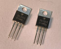
The HG-2SC2312 have arrived.

Finals.jpg

both.jpg

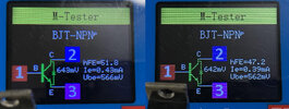
hFE of 47 and 51, quite well matched.

@ DoctorAudio: it was a good tip to get these(y). I replaced both finals and set the bias to 40mA for each (50mA for the driver TR43 according to the manual). I re-did the Tx alignment and now the amplitudes of the RF signals are ok :cool:.

For the AM carrier unmodulated, I have limited the RF output voltage (measured with the oscilloscope on the dummy load) to 65V p-p, corresonding to 10W, right on spec.
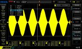
In AM with 100% modulation the excursion is nearly 120V p-p, corresonding to 35W PEP - wow!

AM max modulation.jpg

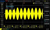
In SSB, with the 2-tone signal on the mic, I get 86V p-p max excursion, corresponding to 18W PEP, slightly short of the 21W in the specs for this kit.

ssb.jpg

I guess this is good enough, but there is still one thing that puzzles me. Why do I get a much higher voltage excursion in RF output for AM than for SSB? In AM I can go even higher than 120V p-p (with 100% modulation) if I turn up the AM carrier power (VR-13). But in SSB I cannot go higher than 86V p-p.

I measured the amplitude at the base of the driver (TR43):
- in AM Tx: 9V p-p
- in SSB Tx: 1.8V p-p

So the signal at the base of the driver is a lot smaller in SSB. I guess this must be the reason, even if in SSB the finals work in class AB, with the full 13.8V DC applied at the collectors.

I should say that I tweaked very carefully the coils upstream of the RF amplifier (L45, L46, L48 and L49) in SSB for max output, so it must be something else...

Any suggestion is welcome!
 
Last edited:

dxChat
Help Users
  • No one is chatting at the moment.