• You can now help support WorldwideDX when you shop on Amazon at no additional cost to you! Simply follow this Shop on Amazon link first and a portion of any purchase is sent to WorldwideDX to help with site costs.
  • Click here to find out how to win free radios from Retevis!

New Sirio Tornado 27

Do your radials stick over the actual roof? If so this is most likely your main issue

222, you make a good point here. I'm at the limit for the number of segments my version of Eznec can use, 500. So, I had to make the antenna simple (no radials) using just a few segments.

I could try lowering the segment count for the roof part of the model, but I don't have a model with horizontal radials that produces a good match, and I don't know how to use the matching feature in Eznec.

I would venture to say if you were to move the antenna away from the metal roof your VSWR would go down like it should.

I think my model does not fix the SWR by either moving the antenna 70' feet away or raising it to 36' feet in height.

But I still would like to see what Marconi's plots show as far as the pattern and any ill effects the roof might have.

I've not been feeling well 222, and analyzing these models take concentration. I hope to finish later today. Maybe I had too much cigarettes, whiskey, and wild wild women over the New Years celebrations.:ROFLMAO:

The roof isn't ideal but I wouldn't call it an issue.

So far in my considering my model of the situation here...I agree with 543 on his point.

The best place to fine tune it is where it will be used. That takes more work though.

I totally agree with 543 here, you just can't beat tuning at the working location and height.

Asuming your coax and connectors are in good shape and your meters are ok. I'd be willing to bet a common mode choke below the feed point will bring your readings closer together. If your SWR changes as a result it means you needed it.

I wish I had the confidence to make a feed line choke that worked on this model. If you have enough feed line, I would check 543's idea out by coiling a choke using the feed point end of your working feed line.

I'm not sure about the Tornado 27 and CMC's, but I would like to model it...if somebody can give me all the necessary dimensions to do a good model. IMO this vertical dipole I'm using here is prone to CMC. Sometimes raising an antenna changes things.
 
  • Like
Reactions: 222DBFL
Dallas you mean roll up some coax below the antenna? Like how many laps? I probably only have about 6' of coax to spare without lowering the antenna some.

That should be enough. You need a 4-5 inch form with 4-5 wraps. If you're using lmr400 or something not so flexible don't wind it too tightly and damage the coax. I prefer use a stack of ferrite cores vs wrapping the choke. I don't know the mix but these have proven to be effective at 27mhz. There are 4 or 5 on my base antenna and a few in the headliner of my truck at the puck mount. At one time I had a 12 pill with a poorly mounted antenna on my truck. A couple of those right under the mount stopped 90% of my RFI. I almost couldn't believe it. Wrapping them in tape keeps the sun from destroying them. Wrapping a choke works fine if it's done correctly.

http://www.frys.com/product/343175;...qZtji5upA__.node1?site=sr:SEARCH:MAIN_RSLT_PG
 
I have been thinking that the metal roof being a given distance under the radials will have far less of an impact than you guys seem to believe. To test this I made a model, and to be sure, I used a larger roof than the one in the picture.

Here is the layout.

layout.jpg


The base of the antenna is a little under 10 feet above the roof, and there is a mast running from the base of the antenna to tip of said metal roof. There is another mast running from that same tip to the earth below, which is set to "Real Ground" with the "Moderate" option.

NOTE: The edges are not cut off, the picture is simply not large enough to show the full pattern.

The impedance of the antenna without the roof is 77.4 - j286, and the impedance for the antenna with the roof is 75.6 - j290.

When it comes to efficiency, the antenna by itself has a radiation efficiency of 61.46, while the antenna over the roof has a radiation efficiency of 62.77.

Now to look at radiation patterns. First the horizontal pattern.

hp.jpg


Now the vertical pattern.

vp.jpg


And the 3D pattern for gain for the roof model.

3d.jpg


As we can see the antenna over the metal roof still has descent low angle gain in all directions. In the direction of the roof it has also has a high angle lobe.

Hope this is useful to you guys.


The DB
 
Ok I had to lower the antenna it is now 17'8' off the ground and just over 5' above my roof. I added the choke and now the SWR is 1.2 Ch1 1.4 Ch40 I added a pic also of the choke.
 

Attachments

  • Choke.jpg
    Choke.jpg
    197.1 KB · Views: 13
Last edited:
Ok changed it again with same results. Took out the choke and put it right at 20' dead on and my SWR is same 1.2 and 1.4. Sorry for so much changing just trying out different things. I'm leaving it there because my pole is more stable then raising it all the way up. Radials are 7'11 above the roof. I dont think that is a 30' pole so it Might have been at 26' originally not 30' I'm done for now until I can get it down with some help and lower the top section. The thing is the radio meter dont show it under 1.2 on any band lower than 11 meter. So the best I could do is lower top to match it 1.2 across 11 meter band. Unless if you keep lowering it the bottom number starts to lower also. I dont know how that works.
 
Last edited:
I have been thinking that the metal roof being a given distance under the radials will have far less of an impact than you guys seem to believe. To test this I made a model, and to be sure, I used a larger roof than the one in the picture.

Here is the layout.

layout.jpg


The base of the antenna is a little under 10 feet above the roof, and there is a mast running from the base of the antenna to tip of said metal roof. There is another mast running from that same tip to the earth below, which is set to "Real Ground" with the "Moderate" option.

NOTE: The edges are not cut off, the picture is simply not large enough to show the full pattern.

The impedance of the antenna without the roof is 77.4 - j286, and the impedance for the antenna with the roof is 75.6 - j290.

When it comes to efficiency, the antenna by itself has a radiation efficiency of 61.46, while the antenna over the roof has a radiation efficiency of 62.77.

Now to look at radiation patterns. First the horizontal pattern.

hp.jpg


Now the vertical pattern.

vp.jpg


And the 3D pattern for gain for the roof model.

3d.jpg


As we can see the antenna over the metal roof still has descent low angle gain in all directions. In the direction of the roof it has also has a high angle lobe.

Hope this is useful to you guys.


The DB

Thats pretty neat you can do that. Thanks for the info.
 
I just thought of something else. If I grounded the mast would that help any? There is about a 4' old pipe pounded in the ground its setting over on the ground to hold the bottom but I wouldn't consider that grounded.
 
I would ground it for lightning safety but it's not going to help your RF situation. If there is common mode and you run a ground wire down to the ground you might see some change for the better or worse but doesn't actually fix anything. It should definitely be grounded for safety though.
 
  • Like
Reactions: Galaxy 959
Ok I had to lower the antenna it is now 17'8' off the ground and just over 5' above my roof. I added the choke and now the SWR is 1.2 Ch1 1.4 Ch40 I added a pic also of the choke.

The choke needs to be done like this. Just rolling it up does not work very well.
 

Attachments

  • choke.jpg
    choke.jpg
    5.8 KB · Views: 10
  • Like
Reactions: Galaxy 959
great antenna when going..
however this is my experience with the sirio tornado 27 5/8

mine broke 3 insulators over 12 months ..first one blew out in a close by lighting strike 6 weeks into ownership..this is where a dc ground would of "helped" to prevent this

second broke in 120km winds two weeks after replacing the first one with a new one (i live in high wind area exposed to coastal winds

third new insulator broke while antenna was laid down for yearly maintenance by this stage it was 12-13 months old
(no it did not hit anything it was just horizontal and the weight of the radiator cracked the insulator
then i grew up and brought a shockwave and not one issue
 
  • Like
Reactions: Galaxy 959
I prefer use a stack of ferrite cores vs wrapping the choke. I don't know the mix but these have proven to be effective at 27mhz. There are 4 or 5 on my base antenna and a few in the headliner of my truck at the puck mount. At one time I had a 12 pill with a poorly mounted antenna on my truck. A couple of those right under the mount stopped 90% of my RFI. I almost couldn't believe it. Wrapping them in tape keeps the sun from destroying them. Wrapping a choke works fine if it's done correctly.

http://www.frys.com/product/343175;...qZtji5upA__.node1?site=sr:SEARCH:MAIN_RSLT_PG

How and what do you find effective at protecting these clamp on ferrite cores?

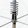
I'm interested in making a detailed model of this antenna including the matching coil, but I don't have good dimensions and I'm not sure how the coil area, insulator looking black device inside the coil is setup.

Does the coil section of the antenna, noted at the left of the image below, come assembled, except for the radials?

Is this base assembly section all metal from top to bottom or is the top isolated from the bottom inside the black boot looking area?

I'm not sure what continuity I would find in the coil area or the feed point either. I've heard the antenna does not have a direct path to Earth ground.

Can you help me?

great antenna when going..
however this is my experience with the sirio tornado 27 5/8

Yeti, same questions for you.

Here is the image. I added my estimates for the dimensions I need...if that is helpful.
 

Attachments

  • IMG_0001.pdf
    144.3 KB · Views: 10
How and what do you find effective at protecting these clamp on ferrite cores?

I'm interested in making a detailed model of this antenna including the matching coil, but I don't have good dimensions and I'm not sure how the coil area, insulator looking black device inside the coil is setup.

Does the coil section of the antenna, noted at the left of the image below, come assembled, except for the radials?

Is this base assembly section all metal from top to bottom or is the top isolated from the bottom inside the black boot looking area?

I'm not sure what continuity I would find in the coil area or the feed point either. I've heard the antenna does not have a direct path to Earth ground.

Can you help me?


Yeti, same questions for you.

Here is the image. I added my estimates for the dimensions I need...if that is helpful.

I've been wrapping the cores in electrical tape to keep the sun from damaging the plastic. I stumbled across these cores by accident at a local store.

I haven't put my hands on one of these antennas so I don't know any specifics. It does appear to be DC grounded via the coil.
 
Yeti, same questions for you.

Here is the image. I added my estimates for the dimensions I need...if that is helpful.

i dont have the dims and reluctant to disassemble the remaining insulator as its a tight fit and easy damaged in the process ..however this is what it looks like inside
sorry for crude paint pic but cant be bothered firing up the CAD
yes coil is on antenna when you buy them ..the rod from so239 to bottom of coil is brass and the rod at top of coil to radiator is also brass (ring that attaches it to radiator is also brass )

the antenna is NOT dc ground in any way
 

Attachments

  • Untitled.jpg
    Untitled.jpg
    25 KB · Views: 16
  • Untitled.jpg
    Untitled.jpg
    52.7 KB · Views: 15
  • 20151021153428-tornado_coil_max.png
    20151021153428-tornado_coil_max.png
    273.9 KB · Views: 17
Last edited:

dxChat
Help Users
  • No one is chatting at the moment.
  • @ kopcicle:
    If you know you know. Anyone have Sam's current #? He hasn't been on since Oct 1st. Someone let him know I'm looking.
  • dxBot:
    535A has left the room.
  • @ AmericanEagle575:
    Just wanted to say Good Morning to all my Fellow WDX members out there!!!!!