• You can now help support WorldwideDX when you shop on Amazon at no additional cost to you! Simply follow this Shop on Amazon link first and a portion of any purchase is sent to WorldwideDX to help with site costs.
  • Click here to find out how to win free radios from Retevis!

No receive and other issues on Cobra 29 NW ST

Well, Amazon has "Radioshack" 6A 50PIV diodes $8 plus Extortion Fees. (Prime)

Just put in Radio Shack 6A 50PIV in the search engine.

This will get you by, but DigiKey has other types too.

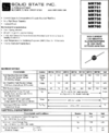
MR750 series (50PIV and Goes Up from there in stages to MR760

Heres a clip of that datasheet...
1644769228748.png
80 cents apiece minimum immediate quantity of 20 you should be good to go.

 
  • Like
Reactions: JDE
Well, Amazon has "Radioshack" 6A 50PIV diodes $8 plus Extortion Fees. (Prime)

Just put in Radio Shack 6A 50PIV in the search engine.

This will get you by, but DigiKey has other types too.

MR750 series (50PIV and Goes Up from there in stages to MR760

Heres a clip of that datasheet...
View attachment 57300
80 cents apiece minimum immediate quantity of 20 you should be good to go.


Andy, will the ones I linked at the bottom of my last post work? Their base price is $0.48-0.60/each and actually in stock at digikey (not marketplace) so I can get them faster.
 
Oh yeah, but in case of non-immediate or sold out, look around the site using it's search engine. Can help in a pinch.

It's a diode, so they better have some in stock...:LOL:

I was using the engine the site has, so you can investigate some of the older stock that although has a "minimum quantity" requirement - some of the stuff you were looking at needed quite an up-front investment - at 45 cents each with a minimum of 1,000 to order and a waiting time of up to 32 days - might seem a bit too much for a little guy (like me) to take on a simple repair for $450.00 + shipping.
1644773987843.png
...your coffee is getting cold...​
Now if you worked for a plant and needed more of those diodes because of the need for protection - that is a viable order to make for the cost per unit then drops for the price of the radio it's used in, it's spread across the stocks' production.
 
Last edited:
  • Like
Reactions: JDE
Ordered replacements for C123, D23, and D11.

At this point the 29 NW ST has no D11, D23, or C123. Talkback resistor and JP36 swing kit cap/resistor removed. PA works(Dynamike controls the volume), still no receive.

Haven't tested int speaker wiring for output to determine if radio issue or dead speaker, and the meter is definitely dead.

Haven't dug in to the NW panel illumination yet.

No TX tests done yet, other than knowing when I key the mic the speaker circuit shuts off and the red TX light comes on. I have another radio here that I believe has RX, could use as a monitoring radio for this 29 NW ST but I'm not sure how the two should be set up to work like that. Will the monitoring radio, with or without antenna, pick up stray RF from the nearby bench radio TXing in to a dummy load?
 
Will the monitoring radio, with or without antenna, pick up stray RF from the nearby bench radio TXing in to a dummy load?

Yes, it would - you can also make up a Separate Dummy load for the one you'll be using as a receiver. You can then place a long wire onto the center of the SO-239 with the 50Ω load across it to ground.

This would make the receiver (your monitor radio) more aggressive (able) to listen for weaker signals.

Do you have any working schematic for this NW Radio?
 
  • Like
Reactions: JDE
Yes, it would - you can also make up a Separate Dummy load for the one you'll be using as a receiver. You can then place a long wire onto the center of the SO-239 with the 50Ω load across it to ground.

This would make the receiver (your monitor radio) more aggressive (able) to listen for weaker signals.

Do you have any working schematic for this NW Radio?

I currently have a 29 LTD Classic on the far end of the bench set up with power and a small magmount antenna. Only have one mic, though. Got another HG M73 on the way from Amazon. Bench radios go in to an MFJ dummy load that I pulled from the parts bin in my ham shack, might have another I can use for the receive radio.

I do not have a schematic or really any info for the 29 NW ST. All the cbtricks mirrors have them for the 29 LTD/ST/WX chassis but none for the 29 NW or 29 NW ST.
 
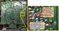
They use the same "main PCB and layout" but the NW takes up a spot on the front panel knobs with its "dimmer" which takes out the DeltaTune - hence the only one Varactor I see on the main Foil side...
1644789783505.png
So instead of a variable Varactor, the Dimmer knob now replaced the Delta Tune and controls the backlit display.

You may or may not have a functional display - these work when they are not punished or abused, but age, fingerprints - oils and pressure - torque from the faceplate - distorts and bends and destroys parts of the EL "sandwich phosphor" used to illuminate. Abuse can destroy the EL-panel Buck converter to power the 40 to 60V needed to light that panel.

They may have disconnected it when they worked on it then when reassembled - it got noisy and felt it was better off not getting in the way of their receive.
 
  • Like
Reactions: JDE
They use the same "main PCB and layout" but the NW takes up a spot on the front panel knobs with its "dimmer" which takes out the DeltaTune - hence the only one Varactor I see on the main Foil side...
View attachment 57302
So instead of a variable Varactor, the Dimmer knob now replaced the Delta Tune and controls the backlit display.

You may or may not have a functional display - these work when they are not punished or abused, but age, fingerprints - oils and pressure - torque from the faceplate - distorts and bends and destroys parts of the EL "sandwich phosphor" used to illuminate. Abuse can destroy the EL-panel Buck converter to power the 40 to 60V needed to light that panel.

They may have disconnected it when they worked on it then when reassembled - it got noisy and felt it was better off not getting in the way of their receive.

The more I learn about the NW illum, the more it sounds like it's not worth digging in to unless it's an obvious and easy fix. That's fine with me, as long as I can get the radio itself working that's all that matters.
 
Correct, best to get the engine running than to spend time fixing a light bulb that doesn't do anything...

The Nightwatch issue can be resolved, tinkered with - at a later time when you have the stamina and have more experience on how this radio is put together.

While I have you here, how are you at Test Points and Alignment?
 
  • Like
Reactions: JDE
Correct, best to get the engine running than to spend time fixing a light bulb that doesn't do anything...

The Nightwatch issue can be resolved, tinkered with - at a later time when you have the stamina and have more experience on how this radio is put together.

While I have you here, how are you at Test Points and Alignment?

If I'm told to measure this component or test for voltage at that lead, I'm capable of using a DMM and looking for components on a PCB or in a schematic.

I don't own a scope, signal generator, spectrum analyzer, or wattmeter and I'm a few days out from having the ability to tx/rx with my monitoring radio setup(down a mic, one on the way). For now I'm trying to keep it simple, focus on diagnosing and repairing the core functionality of the radio and build some knowledge before I get to that step of throwing money at a garage-lab so I can do the serious alignments and measurements.
 
Actually, you should be ok just to look at voltages.

The PLL uses the Channel selector to decide a frequency to look at from the VCO - to obtain that frequency the PLL works with the VCO - using the Varactor - to obtain that frequency.

(It's why I showed you the foil side of the board, you appear to have everything you need, and you also have a RED TX light - which would not have been the case if the radio was not in lock.)

So to do that it starts by sending a voltage to it, and the Varactor is biased using this voltage - just it's reverse biased - shows a high impedance to the flow of power thru it - which is great, because the Varactor is special for a purpose of having to exhibit capacitance - a capacitance that changes as voltage with no power (no current - high impedance) is applied, a transistor set up to run as an oscillator then can take this capacitance and use a coil in its circuit support, and make it "squeal" at a specific frequency that changes with the voltage across that varactor.

The Higher the Voltage - the Higher the Capacitance value the Diode has - this then forces the oscillator to "slow down" - but how does the PLL know this?

That is where the "Loop" comes in.

The PLL uses the 10.240 crystal as a clock and as a source for timing - and the channel selector as a means to divide the timing signals to a point where a loop on one side VCO, can be compared and adjusted by a loop on the other -PLL Local Oscillator.

So, what you need to know is if the radio can show a RED light, do I have any signal or power to make the TX side work?

Thats is where a DVM can come into play, and you can see the "LOCK" function by seeing the voltage at that test point go up and down as you tune the slug for the Varactor.

So go back to those threads and look for those "test points" and the associated graphics - you'll see where to hook up your leads and check for the Voltage at the test point, change the channel too from 1 to 40 - that voltage changes, or at least it should.

I'll stop here and let you figure out your notes and how to develop a plan for your effort to fix this thing.
 
  • Like
Reactions: JDE
Actually, you should be ok just to look at voltages.

The PLL uses the Channel selector to decide a frequency to look at from the VCO - to obtain that frequency the PLL works with the VCO - using the Varactor - to obtain that frequency.

(It's why I showed you the foil side of the board, you appear to have everything you need, and you also have a RED TX light - which would not have been the case if the radio was not in lock.)

So to do that it starts by sending a voltage to it, and the Varactor is biased using this voltage - just it's reverse biased - shows a high impedance to the flow of power thru it - which is great, because the Varactor is special for a purpose of having to exhibit capacitance - a capacitance that changes as voltage with no power (no current - high impedance) is applied, a transistor set up to run as an oscillator then can take this capacitance and use a coil in its circuit support, and make it "squeal" at a specific frequency that changes with the voltage across that varactor.

The Higher the Voltage - the Higher the Capacitance value the Diode has - this then forces the oscillator to "slow down" - but how does the PLL know this?

That is where the "Loop" comes in.

The PLL uses the 10.240 crystal as a clock and as a source for timing - and the channel selector as a means to divide the timing signals to a point where a loop on one side VCO, can be compared and adjusted by a loop on the other -PLL Local Oscillator.

So, what you need to know is if the radio can show a RED light, do I have any signal or power to make the TX side work?

Thats is where a DVM can come into play, and you can see the "LOCK" function by seeing the voltage at that test point go up and down as you tune the slug for the Varactor.

So go back to those threads and look for those "test points" and the associated graphics - you'll see where to hook up your leads and check for the Voltage at the test point, change the channel too from 1 to 40 - that voltage changes, or at least it should.

I'll stop here and let you figure out your notes and how to develop a plan for your effort to fix this thing.

I can hold off on determing if TX works or not until that mic gets here later this week so I can do that test with my other cobra and go from there. The main issue is that I have no receive, but PA works, so it's presumably not the audio circuit.

I have been trying to collect notes on all the usual test points and expected values, to get them all in to one document for easier access...but info is scattered all over the place and it's proving difficult to find haha.

Edit: I do a LOT of documentation/KB article writing at work. As I'm researching and learning troubleshooting steps and techniques, I'm documenting everything to come up with sort of a Cobra 29 ELI5/For Dummies/Cheatsheet of common issues and simple workflows to determine the faulty component.
 
  • Like
Reactions: Handy Andy
To help:

Since the radio uses two sets of frequencies to obtain the RX, you can short Pin 1 to Pin 4 on a more dedicated basis and avoid the handset - just so you can hear the speaker and tune in on the IF hiss noise present in a typical CB receiver.

It's why I recommend the Test Points and get to know you more moment with the radio. It's not necessary to get the TX to work, for if you can verify the radio is working thru the test stages - then TX will "drop in" and the radio will work with very little effort to make any tuning adjustments.

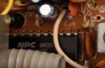
But then too, one thing I wanted to point to dealing with the AGE of this board...

1644798897505.png
That PLL was made back BEFORE 2000 - 1996 - 5th week - and NPC has not been in these radios since the 2000's when Cobra migrated to the offshore areas, we see the origins now.

Why do I point this out?

Might need a few of those Electrolytic caps replaced or at least do those voltage checks to find the areas with no or low voltages, for they are the ones you'll need to get right to make the radio work normally - the poor caps get old and as they do act more like resistors pulling power and signal away to ground.
 
Last edited:
  • Like
Reactions: JDE
Is there a specific thread you're referring to that has all those test points and expected values I should be looking for? Having a bit of trouble finding that info.

Also, any further reading available for that NPC 9605? I'd like to know more about that component, and if it's something that can be replaced/upgraded.
 
  • Like
Reactions: Handy Andy
NPC is a brand - 9605 is the Date Code - you break down that number in groups.

First two are last two digits of the year it's made - in this case '96 or (19)96

The second group is the week of the year - 52 weeks in a year, 05 means 5th week.

The chip is a D2816 PLL or equivalent.

The radio still has a lot of the old OEM capacitors that can add issues to the mess you already have.

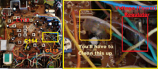
Since you're getting a RED TX light - it indicates something is working to even let the PLL turn that LED on - doesn't always do it but if the radios' PLL is healthy, the RX is not - tells me one or two caps the feed the power from the main Regulator that is over by the Audio chip - might be failed.

1644852840008.png

You saw how C123 was, these caps are no different.

1644852657982.png
1644852893440.png

Try looking for and replacing...C119 by Power Regulator (Above) and C114 by front panel PLL and C112 by PLL and TX side L19 - these work the main voltage Regulator that runs both the PLL and much of the Mic, TX and RX side for regulation and a clean power feed in key spots for the radio.

Time to get after those hot glue spots.
 
  • Like
Reactions: JDE

dxChat
Help Users
  • No one is chatting at the moment.
  • @ BJ radionut:
    EVAN/Crawdad :love: ...runna pile-up on 6m SSB(y) W4AXW in the air
    +1
  • @ Crawdad:
    One of the few times my tiny station gets heard on 6m!:D
  • @ Galanary:
    anyone out here familiar with the Icom IC-7300 mods
  • @ Crawdad:
    7300 very nice radio, what's to hack?