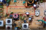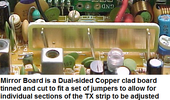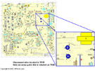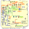
This is for a 33HML (3 position switched Hi-Mid-Low power) but you do get the layouts.
The Voltage reading is important - it determines if you even get 6 watts.
At 5.6 volts - you should be between the 4~5 watts - if you're not getting that then there are issues, but I wanted to stop and ask about your Bird 43 - if you trust this meter - then the fuss is about the Galaxy not showing the meter the modulation?
Ok, Modulation on the 43 Bird, or are you looking at swing?
Then there are more mods we haven't found or uncovered - again, I'll have to defer this to those that started with you on this as I go over the posts with all the mods they did find.
No one seemed to care about the "dual final" - so did this get a IRF520 or does it still use the older Bipolars and what ones are being used?
Sorry can't read those numbers on this end.
Why would it matter - you're having trouble trying to get modulation - and by what I see this SHOULD have the MOSFET mod done to it for just this reason...
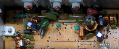
The coupling cap should be a 1500pF or 152 - that cap in there now is quite large so knowing this and below the board on the foil side - there is another cap that straddles this one - looks like to pass as much RF to the next stage (Final section) So to me this is a MOSFET converted radio.
Doesn't explain the "low mod" issue except for that once you remove TR32 limiter - the modulation seems to come back.
- Again, understand that we are working on a radio once considered stock worked one way and had less components in the TX strip than it uses now.
- We do not know of the condition of these parts - only that tests by your showed they worked to a point
- There are still more mods to the radio that unless we can see them - we can only guess at what you should do next.
IF you want my opinion - and not everyone does - but to help you more requires more rework, this may need to involve a shop that you need to trust so they can rework the radio to match the new components more closely.
The crux here is the General Lee used a board that can take in this MOSFET and two finals conversion - but the component list used values for SINGLE Bipolar final.
One aspect here is carrier control - the 14B versus the 14C - when the power levels were changed on the older boards - the AMC had to change its operational window as well - the 14C and 15 versions and above worked AM Power level as a RATIO of used voltage (Carrier) to drive (Modulation), to the level of modulation - so they tried to make the window correct by using FIXED values as long as the AM power the radio inside used - and pre-set - the radio will work in a specific way and predictable.
Someone's been in there and added a few more things but haven't corrected the condition - to tell you exactly what to do from this moment on requires a shop that knows Galaxy chassis like this.
Ok, we now know there are TWO MOSFET and One Driver also should be some type of MOSFET - so the weak modulation then comes from the AM Pass transistor used - located on the side panel side where you found two Transistors that get very warm.
The one at mid-point of the board panel side is the VOLTAGE REGULATOR - you might want to upgrade this or at least look into previous posts about Galaxy Mods to find drop-ins that can work here. The used to use a 2SA473 - but others have used TIP series with some success
The one towards the back - by that long flat chip (Audio Amp) is the AM Regulator - being the one that pushes the modulation into that Jumper and TX strip.
If that has not been upgraded - then at least look at the numbers printed on it so we can find a suitable replacement for it. IT may be your whole problem (in context but see above) .
Some MOSFET mods KEPT the original AM Regulator - and just jumped the Final with 12V to save trouble at the cost of some modulation effect This worked for many a SSB and FM user - but not so much the AM crowd because it needs linearity (volume) in the carrier signal to push the modulation in the envelope.
So some choices have to be made.
