• You can now help support WorldwideDX when you shop on Amazon at no additional cost to you! Simply follow this Shop on Amazon link first and a portion of any purchase is sent to WorldwideDX to help with site costs.
  • Click here to find out how to win free radios from Retevis!

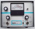
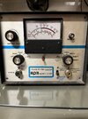
Pace P-5430 Radio Tester

yorkiebar

New Member
Apr 20, 2023
3
0
1
72
I am new to the forums, so my apologies if I get things wrong.

I have a Pace P-5430 Radio Tester and need a service manual or at least a schematic for it.

I have looked on the internet but can find nothing, which I find incredible.

Can anyone help please......
 

Attachments

  • pace-p-5430-two-way-sw-radio-tester.jpg
    pace-p-5430-two-way-sw-radio-tester.jpg
    34.2 KB · Views: 9

I have one of these I procured in the early to mid 80's. I have been unable to find a service manual or schematic myself.
I have added a small toggle switch to kill battery power when not in use and have aligned it with an oscilloscope for power readings only. It works well for what I use it for but the Field Strength meter has never worked.
Sorry I can't offer any help but a decent piece of gear for a quick on-the-fly indicator.

73
David
 
Hi David
Many thanks for coming back to this plea for help.
When I purchased this item and looked inside it had a PP3 battery clip but it was not connected to anything at all and I don't know where to connect it to.
If you could help with this and possibly a picture, that would be great
Kindest regards
Jamie
 
David
Would I be right in thinking that you have removed the antenna wire from top of cabinet and placed positive from battery via switch to where center core on antenna cable was ?
Jamie
 
Jamie,
No.That is not correct.
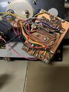
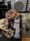
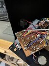
The battery hooks up to the main circuit board ground (Battery negative) and the battery positive lead hooks to the circuit board just below the purple wire on the circuit. Look closely at the 2nd picture. The red wire from the circuit board attaches to 1 terminal of the switch the from the 2nd terminal of the switch to the battery clip-positive. In the 4th picture there is a screwdriver tip under both the battery wires.
I did not know that the yellow wire was not connected to the antenna connector until this morning when I opened up the unit to take a picture. It could have broken loose from the antenna connector when I opened it. The solder connections were not the best I have seen even when I got this unit.

73
David
 

dxChat
Help Users
  • No one is chatting at the moment.