• You can now help support WorldwideDX when you shop on Amazon at no additional cost to you! Simply follow this Shop on Amazon link first and a portion of any purchase is sent to WorldwideDX to help with site costs.
  • Click here to find out how to win free radios from Retevis!

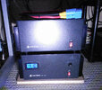
Parallel Operation of 2 Astron RS-70's ...

Well ... I finally have THE answer, from Astron tech support nonetheless. I hooked up my supplies as per the last recommendation (ie. load on POS of one supply and NEG on the other). I was noticing some funky behavior between the two but was getting output. I hooked up a test load and all was well, but still funky. I decided to call Astron tech support and get a clarification. Fred instructed me in this fashion;

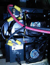
1. bridge the supplies; + to +, - to -
2. hook up load to + on PSU #1, - to PSU #2
3. hook up 20 gauge wire between the parallel connection posts.

Looks like the answer was not one or the other, but BOTH. Now that I think about it, this makes the most sense.


ok i agree with #1

i question only WHY regarding #2. if they are bridged, they are bridged. if you draw power from a common point-even a bus bar bridging via equal lengths of equal guage cable-i'm not sure what the difference would be. i've run batteries in parallel for many different applications over the last 35 years. never have i been told to take + from the 1st battery & - from the last. i've also run parallel power supplies since the 1970's & the same holds true. i've run power cables from a bus bar as well as from + & - of the same supply with no negative results.

as for #3, did the tech explain what that 20 guage wire is controlling internally on the astron PS?
 
- i question only WHY regarding #2.
- as for #3, did the tech explain what that 20 guage wire is controlling internally on the astron PS?
My theory would be that there is no master/slave relationship in this configuration. I would then think that there would be load balancing. I read other posts of this not occurring. The other posts mention of one PSU being driven to max before the other starts to contribute.

I didn't ask about the details of the parallel connection wire, I was still in amazement from the details of the hook-up he just explained to me. A good question that still needs answering.
 
the idea behind taking -v from one supply and +v from the other is to minimise current sharing issues that any volt drop on the jumpers could cause if you take - & + from one supply and jumper to the second supply,
it only takes a small vdrop on the jumpers to cause one supply to do most of the work.
 
  • Like
Reactions: 1 person
the idea behind taking -v from one supply and +v from the other is to minimise current sharing issues that any volt drop on the jumpers could cause if you take - & + from one supply and jumper to the second supply,
it only takes a small vdrop on the jumpers to cause one supply to do most of the work.


Exactly. I was going to say the same thing after reading Mike's comment from Astron. Apparently this insures that both supplies are working into the EXACT same resistance.
 
  • Like
Reactions: 1 person
now that they are connected together can you run just one if your not needing that many amps, do they need to be turned on at the same time?
 
now that they are connected together can you run just one if your not needing that many amps, do they need to be turned on at the same time?


If one was not turned on then essentially you have one set to the proper voltage and the other set to zero which is NOT the procedure. Run them both. The gear will only draw whatever current is required.
 
now that they are connected together can you run just one if your not needing that many amps, do they need to be turned on at the same time?
For curiosity's sake I turned one PSU off and the load was still powered on in a idle state. Although, these PSU's are not doing anything else but power this one load which requires the current of two, so the point is moot ... they both remain on.
 
This have been confirmed. I've hooked everything up as per above and works like a charm.


And, I just re-confirmed it. Spoke with a fellow at Astron, then, a bit later, spoke with a close friend, who has been building, repairing and modifying, power supplies, for 12-13 years.
Both, said that this is the correct procedure. I just connected my RS-70A, and RS-70M, in this manner, to power a Kenwood 480, with an SGC-500 Smart Cube.

Works like a champ! 650, honest, clean, watts, out, on 40M, measured on a Bird 43.
 
Normally when you jumper the posts in the back labeled for parallel operation only the voltage regulation and hence output is controlled by one of the supplies. It becomes the master and the other is the slave. Normally with these there is no need to balance the voltage but since you modded one all bets are off on that one. The reason i didn't chime in earlier was that i have heard two different ways to hook up the dc. One says to bridge them as you did the other says to take the pos from one and the neg from the other. Never ran two astrons before so i couldn't say.

This! As per my telephone discussion with an engineer at Astron this morning. +load to one Astron and -load to second Astron, after bussing both Astron ++ --
Mark KX8XX
 
Do any of the Astron manuals describe how to do it? I could swear that I read about it a long time ago. I've never seen anyone do it. Might send them an email or call them.

I read an old thread on Fwed's site, they all seemed confused and in disagreement.
I know I read it as well & I thought it was in the manual to the RS-70M but I have no idea where that manual is since I no longer have that supply. I know I did not dream it.
 
from Astron manual . . .
 

Attachments

  • Astron Power Supply parallel hook up.jpg
    Astron Power Supply parallel hook up.jpg
    618.7 KB · Views: 97

dxChat
Help Users
  • No one is chatting at the moment.