• You can now help support WorldwideDX when you shop on Amazon at no additional cost to you! Simply follow this Shop on Amazon link first and a portion of any purchase is sent to WorldwideDX to help with site costs.
  • The Retevis Holidays giveaway winner has been selected! Check Here to see who won!

PC66 with ??? Channel expander.

MKwrench

Member
Aug 6, 2023
25
15
13
53
I like these old PC66s and grab them up when they are cheap or "for parts".
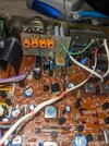
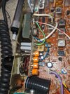
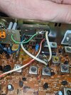
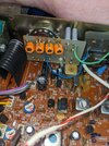
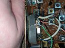
This one has a channel mod that was installed improperly. It wouldn't transmit or receive when I first tried it out. The ground and input were reversed on the "switch/xtal" board to the add-on "tune board". After reversing these and cleaning up the switch contacts, I was able to transmit on all 4 "band" positions on the switch. Position C, was the 27 megahertz CB band which I'm most familiar with so I tuned that first. Band D continued with 27.415, I hadn't yet messed with bands A and B.
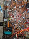
When I tried to tune receive, It wouldn't allow me to achieve peak on any coils without it dropping back down to nothing, like the AGC was killing everything even at -110dbm. I noticed that, for appeared to be the power supply wire for the add-on boards went to + of c-36 (measured 12v), and was probably milking power from the receiver. (???). I moved this wire to the switched side of the power switch, and was able to tune the CB band (C) in both transmit and receive absolutely perfectly, but now have nothing on A B and D.
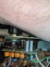
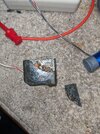
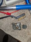
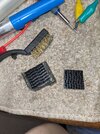
Is anyone familiar with, or can recognize this "add-on board"?
I'm going to try moving that power wire to an 8 volt supply near the regulator, to see if it makes any difference, but I can't get back to this for another 3 days. It would just be cool to hop back into this thing with some extra insight.
Thanks guys, you've all been a great source of knowledge in the past!
 
  • Like
Reactions: Cable Guy

I forgot to add pictures.
The pictures are the best part!
Does anyone recognize these?
I can't get back to this radio untill Thursday to try the 8V supply, It looks like I could add a ground besides the one in the "mini coax". What are your thoughts on this?
 

Attachments

  • PXL_20241217_002913226.jpg
    PXL_20241217_002913226.jpg
    3 MB · Views: 11
  • PXL_20241217_002922594.jpg
    PXL_20241217_002922594.jpg
    3.2 MB · Views: 11
  • PXL_20241217_003435306.jpg
    PXL_20241217_003435306.jpg
    3 MB · Views: 11
  • PXL_20241217_003439930.jpg
    PXL_20241217_003439930.jpg
    3 MB · Views: 11
  • PXL_20241217_003454552.jpg
    PXL_20241217_003454552.jpg
    2.2 MB · Views: 11
  • PXL_20241217_003507342.jpg
    PXL_20241217_003507342.jpg
    2 MB · Views: 11
That radio uses an Expo S kit and i have installed plenty of them in the cobra 25s.
problem is the best you will get is 40up and 40 down. The radio is not made to broadband 5 bands unless you have some type of powered added vco to broaden the range of the channels. I was doing the cobra 29s with wit 80 up and 40 down could never get the radio to about 60 chs above 40. so try to tune the radio to 40 high and 40 low. Power and receive will drop off fast on the edges.
 
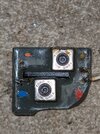
What are the crystal frequencies? There are 2 grey heat shrink covered crystals on the top of the switch board, and looks like 2 more on the bottom of that switch board. They are going into an epoxy covered board that has 2 coils, and what looks like a TA7310 oscillator/mixer IC like what is used for the TX mixer IC2. Not "technically" an Expo100 "S" kit, but maybe similar.
 
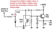
This is how I broadband some radios to increase their frequency range. I had a GE 3-5804D (PLL02A) that went from 25 MHz to 30 MHz, with about .5 watt drop in power from center to band edges, the entire 511 channel bandwidth of the PLL. I made my own FM boards too, on perfboard. It looked like a porcupine with all of the switches, but it was my ongoing experiment radio.


Broadbanding 2.jpg
In the C25/PC66/AX44 etc... this would be C74, 68pf.

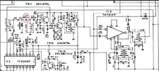
AX44 PLL TX Mixer.jpg

C25 PLL C74.jpg

I had "borrowed" this idea to expand the range of VCO's and used it for the past 40 years, borrowed from Lou Franklin's page on Broadbanding Techniques

https://cbcintl.com/docs/broadbanding.htm

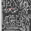
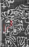
Also, to broadband the TX mixer, move C84 to the unused pin of the front of L18 (solder side)

AX44 Board Layout.jpg

The front coil of the dual coil L18 is now the main active one, and the back one, not so much. I have done this to the same circuit in C29's.
 
Last edited:
What are the crystal frequencies? There are 2 grey heat shrink covered crystals on the top of the switch board, and looks like 2 more on the bottom of that switch board. They are going into an epoxy covered board that has 2 coils, and what looks like a TA7310 oscillator/mixer IC like what is used for the TX mixer IC2. Not "technically" an Expo100 "S" kit, but maybe similar.
Ya, I dont think it's an "Expo" brand kit. Does have 4 Xtals and 4 trim caps, I havn't measured the frequencies yet. I may have damaged the "Epoxy" board by feeding it full voltage, I moved it to 8v, but now have nothing in any band, missing the "front" oscillator now. I'm going to look for trace damage.
 
When I install The S Kit or A Kit its only for 40 above and 40 below i have no problems there. I did try to do 80 above and 40 below on a cobra 29ltd and was able to only get about 20 channels on the 40 + + bands so there is nothing up there and adding 80 extra channels are more than enough i tell people
 
Last edited:
  • Like
Reactions: MKwrench
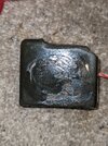
After removing the "epoxy deal" I was able to chip the back of the board clean because the builder forgot to clean up the flux.
After reflowing a few spots, it was working again. I hooked it up with jumpers and was able to tune 26.965-27.405 on "C" and 27.415 to 27.855 on "D" again not touching "A" and "B" yet. I did use full power at the switch, frequencies seemed too low to tune with just 8v supply. (24mhz at the most)
I filled it back in with clear/removable adhesive and added a 3M xtreme fastener.
Band "D" tuned perfectly, But there is a weird distortion in "C"s recieve. I'll add pics of the scope when I get it back together. Here's more pics.
 

Attachments

  • PXL_20241219_143419697.jpg
    PXL_20241219_143419697.jpg
    2.4 MB · Views: 7
  • PXL_20241219_143434649.jpg
    PXL_20241219_143434649.jpg
    2.3 MB · Views: 7
  • PXL_20241219_150201393.jpg
    PXL_20241219_150201393.jpg
    3.1 MB · Views: 7
  • PXL_20241219_170136995.jpg
    PXL_20241219_170136995.jpg
    3.6 MB · Views: 7
  • PXL_20241219_170647669.jpg
    PXL_20241219_170647669.jpg
    3.8 MB · Views: 7
  • Like
Reactions: NZ8N
I ended up swapping out a few suspect caps and put the supply back on 8v with a choke, in case the distortion was from RF bleeding to +.
After I poked around with the scope in a few spots, the distortion went away, but came back after the radio sat a few hours. (time for a full recap ???).
* I really think its just the local oscillators/filters not being in phase with the added stuff. (???)*
We ended up with: 26.065 to 26.505 on Band A, 26.515 to 26.955 on Band B, 26.965 to 27.405 on Band C, and 27.415 to 27.855 on Band D. I centered RX/TX on 26.955. and have minimal loss on the lower end of Band A.
So far I'm happy to have saved another "trashed" radio. We'll get that distortion another day.
Thanks for all of the insight, I'll experiment with the broadbanding soon also. I'll post results here.
This picture shows where I grabbed 8V, and my overkill choke, (the blue wire gets removed) and the cleaned up connections.
The short clip shows the difference in Band Cs receive.
Yes, my "Homboy" Electr-o-Lab, is a pig sty sometimes. LOL!!!
 

Attachments

Last edited:
  • Like
Reactions: NZ8N

dxChat
Help Users
  • No one is chatting at the moment.
  • @ Crawdad:
    One of the few times my tiny station gets heard on 6m!:D
  • @ Galanary:
    anyone out here familiar with the Icom IC-7300 mods
  • @ Crawdad:
    7300 very nice radio, what's to hack?
  • @ kopcicle:
    The mobile version of this site just pisses me off
  • @ unit_399:
    better to be pissed off than pissed on.
    +1