• You can now help support WorldwideDX when you shop on Amazon at no additional cost to you! Simply follow this Shop on Amazon link first and a portion of any purchase is sent to WorldwideDX to help with site costs.
  • Retevis is giving away Radios for the New Year and Every Member is Eligible. Click Here to see the details!

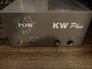
POW KW+ keying circuit

I do have one suggestion. The coax leading from the Load control to the relay does not have the shield braid connected. This was a bad habit somebody must have learned from Maco. Connecting the braid to a ground lug on the Load control, and running a wire from the rear end braid to a ground lug on one of the Antenna jack screws tends to make the driver tuning more stable. I just unwrap a half inch or so of the black jacket at each end without taking anything loose. A short piece of stranded hookup wire gets wrapped around the exposed braid and soldered. The other end of each wire gets grounded at that end.

Whether or not the driver Tune control gets twitchy when you turn it, we ground each end of the output-coax braid as a preventive measure.

73
Hi Nomad,

Thank you for the suggestion! I was wondering if one end would work or both. I will do both, hopefully this weekend. Does the wire size matter when grounding?

73
 
Thanks for the help! Next question… How much drive will this thing take? Not that I’m going to drive it that hard.. Tubes aren’t cheap! I’m just curious.. I tried it with a Grant LT and Galaxy 86V on am.. It doesn’t seem to swing very much.. I may not have it tuned right… It has a knob on the side and tune and load on the front.. So, what is the correct way to tune it?

Thanks!
 

Attachments

  • IMG_2226.jpeg
    IMG_2226.jpeg
    2.7 MB · Views: 80
  • IMG_2227.jpeg
    IMG_2227.jpeg
    1.4 MB · Views: 95
  • IMG_2224.jpeg
    IMG_2224.jpeg
    2.2 MB · Views: 94
First thing to check is for the "twin peaks" on the Plate Tune knobs.

With the Load control set for max modulated power, spin the driver tune on the side. It should show a peak at *TWO* separate spots in one 360-degree turn of the knob. The peaks might be close together, or they might be 180 degrees apart. The important thing is to see that you have two peaks. If there is only one, a glance at the plates on that control will reveal that they are at one or the other extreme of adjustment. Plates fully apart, or fully meshed together. When you see this, the coil attached to that control has to be adjusted. This rule also holds for the front-panel final Tune control.

Until both Tune controls show those two peaks at a spot in between the two extremes of adjustment, you'll typically lose some power.

Running it with either Tune control at "just one" peak can be hard on the tubes.

The tiny adjustment screw on the rear panel gets set with a SWR meter and a coax jumper added between the radio and amplifier. Once it's tuned up for max modulated power, see what the drive-side SWR meter reads. The rear-panel screw is the input tuning and should be set for minimum SWR while the amp is keyed. Makes life easier on the radio.

Any of those can hold back the power.

73
 
  • Like
Reactions: Trainman 8274
If you can only find AC in this amplifier, you've found the problem with the original keying circuit. The amplifier must have DC to run its keying circuit.

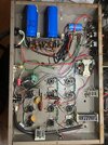
As I took a moment to look at your picture, I can confirm the reason why you have lost dc. Look at the small gray electrolytic capacitor mounted to the terminal strip Behind The Rocker switches. It's positive terminal is snapped off of the anode side of the diode. Leaving Raw DC that will not operate any of the relays properly. Check that capacitor see if you can solder it back or if it needs to be replaced.
Hello I'm an old time CBr with an old sweet tube linear been dragging it around for 30 years hardly used great shape tubes but did a dumb thing it wouldn't key up very easily so I manually tapped the sensor or switch and shorted it and now I can't find anyone to work on these.Pow KW+ Maco?Thanks for any help
 
I manually tapped the sensor or switch and shorted it
Not sure which "sensor" you mean. The relay in the back between the two coax jacks, maybe? It's a switch that's operated by an electromagnet. Called a relay. When the magnet gets current, it pulls a spring-loaded contact lever down and closes the linear's operating circuits. If manually pressing that part caused an overload surge, this is a sign you have at least one failed tube. Maybe more.

If all the parts are original, don't assume all the tubes are okay. Sure, you want them to be, but the odds are not in your favor. Best of luck finding a tech with those skills. Fewer and fewer of them still around every year that goes by,

One thing we have seen more and more often the last ten years or so is that tubes that tested good on a tester will work in the linear for the first dozen keys of the mike, and then there is a "snap" sound and a blue flash from inside one tube. The surge that caused the flash permanently disables that tube. If you don't have more of them it's now dead in the water. Sometimes the surge in the one tube damages one or more of the soldered-in parts, or causes "fratricide" and clobbers another tube alongside it.

Odds are you'll also get advised to change all of the electrolytic capacitors in it. This is because the chemistry inside that type of capacitor just goes bad after a decade or two on average. Yours is closer to four decades or more old. When those parts fail, they can become a short circuit that causes further damage.

Don't know if you have ever been involved in making a 40-plus year old car back into a daily driver. Rubber parts will have to get changed from age alone. Other parts will have to be renewed based on mileage. Your linear is not so different in those respects. Doing just part of the restoration can leave you stranded on the side of the road, so to speak.

Here's a post that shows what was needed to put a Maco 300 back on the air. It's not the same as your POW, but it's roughly the same age.

https://www.worldwidedx.com/threads/maco-300-gets-47-year-tuneup.268043/

73
 
20241221_212727.jpg
20241221_212727.jpg
also this amp has never been keyed up for more than 10 seconds and probably less than a total of an hour total run time when I plug it in the tubes all light up it just doesn't key to fire the full power to the tubes I can show you there's not a burn in them they're like new. Also I appreciate and respect everything you say I'm just adding a little more information really really thanks a lot
 
The 'sensor' is the antenna relay. It passes the connection between radio and antenna straight through while receiving. The small circuit board to its left in the pic has a small blue lump on it. The lump is a smaller relay that enables or bypasses a receiver preamplifier circuit that's alongside it. One of the front-panel switches turns this feature on or off. If it were a Maco, this would be one position of a three-position standby switch. That small circuit board also contains a sensing circuit. When you key the mike on the radio, it "borrows" a tiny sample of the radio's output power and rectifies it to DC. That tiny DC current activates a transistor that energizes the coil in the big black antenna relay. That relay has three circuits, one for the radio coax socket, one for the antenna coax socket and the one in the center is used to shut down the tubes while receiving, and power them up when the relay closes.

And that's what causes me to suspect a failed tube causing an overload. Can't overload anything until you apply high voltage to it. And that's what that center circuit of the relay does when it goes "click" or gets bumped causing that circuit to close.

Over the years now and again an employee would be testing the tubes from a customer's radio or amplifier and find one with a dark filament that just would not light up. I would suggest making a mark on the wall with today's date, since this is such a rare occurrence. That glowing filament is the most-reliable part of the tube. What cause them to fail will be other parts if the structure inside.

One way to see if I'm right is to unclip the spring clip from the cap on top of all the tubes. This will unhook them all from the high-voltage power. Now turn on the power, warm it up and then press the relay's armature down with an insulated screwdriver handle or some other insulator. If it was a tube that made the fuse trip, the power will stay on. This will tell you that it's time to find a tube tester and identify how many of them look perfect, but have a hidden electrical failure inside. My prediction would be more than just one.

The keying circuit, the RF-sensing feature that keys the amplifier when the radio's mike is keyed is famous for going out in that circuit board. It's either a board they bought from Maco, or copied. We learned the hard way to remove it and use a more-reliable keying circuit in its place. The receiver preamp is a bad idea to begin with.

One last bit of bad news. The four large silver cans with two screw terminals each are too old to be trustworthy. They're called aluminum electrolytic capacitors and the chemistry inside that makes the work always degrades after 20 or 30 years. They're no doubt 40 or more years old.

This model has some other annoying quirks that I'll skip for now. Can't even observe them until you can get it to key up and show wattage. No need to borrow trouble you can't observe.

Yet.

Here's a rundown of the typical 40-year tuneup for a similar model, the Maco 300.

https://www.worldwidedx.com/threads/maco-300-gets-47-year-tuneup.268043/

You don't have to go to quite that extent. I just don't like getting called a week or a month after a repair to hear that it has a problem. When one of these goes home, it needs to stay home.

(edit) Whups! Just noticed I posted the link to the 300A refresh twice. Still relevant, though.

73
 
Last edited:
View attachment 71391View attachment 71391 also this amp has never been keyed up for more than 10 seconds and probably less than a total of an hour total run time when I plug it in the tubes all light up it just doesn't key to fire the full power to the tubes I can show you there's not a burn in them they're like new. Also I appreciate and respect everything you say I'm just adding a little more information really really thanks a lot
Just finishing the same amp now. I’ll be happy to take a look if you want to ship. Located in central NC. 460 COMM
 

dxChat
Help Users
  • No one is chatting at the moment.