I have a trc 453, radio is totally stock, it's a garage find, deoxit on all controls and board, radio transmits and receives, has good modulation and on frequency on ssb when listening from another receiver, however.... I can not tune anyone in with the clarifier, it does absolutely nothing as far as varying the radios rx frequency at all also some people on AM also sound funny. I realize this radio is old and has not been used in years, where should i start looking ? someone made mention of "c63 - c64 & c65" in another post similar to mine, would that be correct ? any help appreciated.
You are using an out of date browser. It may not display this or other websites correctly.
You should upgrade or use an alternative browser.
You should upgrade or use an alternative browser.
-
You can now help support WorldwideDX when you shop on Amazon at no additional cost to you! Simply follow this Shop on Amazon link first and a portion of any purchase is sent to WorldwideDX to help with site costs.
Realistic TRC 453 CLARIFIER DOES NOTHING
- Thread starter dirtyjob
- Start date
Are you sure the control really does nothing? I would try a radio with a slider or the ability to move frequency on am and tune around on channel until you can hear the tone from the carrier. Then, move the clarifier on the 453 and see if it changes tone at all. I only mentioned this as if it does change tone on the receive of the 453, then it may point to it needing a frequency alignment.
Yes i am positive, been in radio 35 years, the clarifier knob on this thing does not adjust the rx frequency at all, its like it is a knob hooked to nothing, it does not vary the rx at all.Are you sure the control really does nothing? I would try a radio with a slider or the ability to move frequency on am and tune around on channel until you can hear the tone from the carrier. Then, move the clarifier on the 453 and see if it changes tone at all. I only mentioned this as if it does change tone on the receive of the 453, then it may point to it needing a frequency alignment.
its beyond an alignment, this radio is dead on frequency on am and ssb, its just the fact the clarifier does nothing.Yes i am positive, been in radio 35 years, the clarifier knob on this thing does not adjust the rx frequency at all, its like it is a knob hooked to nothing, it does not vary the rx at all.
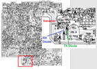
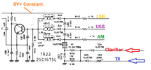
The schematic shows D24 going from the clarifier to X1. I would check that to see if it has failed.
The block diagram shows it listed a D23 sooo...
The block diagram shows it listed a D23 sooo...
and of course check the obvious like a bad pot, broken or shorted wires, bad solder joint etc.The schematic shows D24 going from the clarifier to X1. I would check that to see if it has failed.
The block diagram shows it listed a D23 sooo...
When you say "de-oxit" I cringe at that.
Why?
It can get pretty aggressive and clean the pot, too well - and make the potentiometer useless - for the frequency you're listening to, is on the bottom of the scale - the pot pushes and pulls the power to and from the varactor the IF needs - so if it can't change or won't change - my fear is that the pots composition is gone or the pot has opened up and you don't have control over the frequency in RX - you have a default - that puts it too far outside the normal tracking range and off to one side of the channel.
When the pot works - that power "offset" is put into that pot to change the power the varactor sees - so your "center slot" on the pot is actually a "resistive result" against a fixed array of values as resistors in the system - R118 - it's a 6.8K resistor - or Blue Grey Red body stripe color the other is a 10K Brown Black Orange as R119 - which buffers the input (wiper arm) so it does not load down the circuit.
no deoxit went into the clarifier, i used it on the back side of board and vr controls however. As it stands now the clarifier has no effect on anything making ssb useless because everyone sounds garbled.When you say "de-oxit" I cringe at that.
Why?
It can get pretty aggressive and clean the pot, too well - and make the potentiometer useless - for the frequency you're listening to, is on the bottom of the scale - the pot pushes and pulls the power to and from the varactor the IF needs - so if it can't change or won't change - my fear is that the pots composition is gone or the pot has opened up and you don't have control over the frequency in RX - you have a default - that puts it too far outside the normal tracking range and off to one side of the channel.
When the pot works - that power "offset" is put into that pot to change the power the varactor sees - so your "center slot" on the pot is actually a "resistive result" against a fixed array of values as resistors in the system - R118 - it's a 6.8K resistor - or Blue Grey Red body stripe color the other is a 10K Brown Black Orange as R119 - which buffers the input (wiper arm) so it does not load down the circuit.
You will have to do some disassembly, unsoldering and look, and verify, the pot does have a variable - and that there is a resistance across the terminals.
A pot uses two terminals that give you a fixed resistance, there is a variable resistance across the third terminal when compared to the other two.
That one that varies from the other two when you change the position - one side will increase (in ohmic value) while the other side decreases as you rotate the knob (shaft) if you don't see this, or the pot shows infinite on an ohm meter - then consider the pot needs to be replaced.
If the garbled audio can't be cleared up you may need to do some further repair.
The electrolytic capacitors inside the unit are old, and more than likely dried out and now load down their respective circuits like resistors and not act and work like the filters (open - nearly infinite ESR) they are supposed to be.
IT may be a Garage find, but like anything found in such environments, you'll still have a lot of cleaning up to do and repair that has to be done to it, and it turns into more of a labor of love.
will doCheck for DC voltage on the pot and see if it is even getting any control voltage.
This is a "follow the money" strategy.
A 'scope is my swiss-army knife for one of these. You start at the center lug of the control. Turn the knob end-to-end. If the voltage swings up and down like it should there, you go the diode D24 that it feeds into and see the voltage swing is on both sides of that diode. It will feed into a 10k resistor R116. The side of R116 connected to D24 will show only DC voltage rise and fall turning the clarifier. The other side of R116 will have RF and DC voltage both on it. But only if you use the "X10" side of the 'scope probe. R16 feeds into the varactor diode and one side of the 10.2417 MHz crystal. A "times one" 'scope probe will load down the circuit and stop the crystal from oscillating altogether when the probe touches it. The "times ten" 'scope probe should allow the circuit to continue oscillating so you can see the 10.24 MHz RF on the 'scope.
73
thats where im like the old timers. ask them if they could have only one piece of test gear/had to choose one, they always say an oscilloscope. and i fully agree
Mine would be the DVM - but I also wanted to check back with you on something that I see often (or when I was repairing and modding these things).
It's with D25, D24 and D23 - they may have been trying to install or open - the clarifier - only they didn't finish the job correctly - they may have cut the wrong diode.
IN the TRC453 - two diodes steer power to the Varactor - D23.
D24 if from the RX (Clarifier - you leave it in)
D25 is from the TX (your TX FREQ pot)
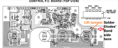
So the proper way to do the mod, is to remove the TX and RX sides and simply put 8V constant into the buffer side of the Clarifier power input and let it ride thru and the Clarifier would work on a single ended power feed.
You Cut D25 (or remove it use it to direct power to the clarifier and provide a inherited voltage drop to help you with recentering the tuning IF coils as needed), On the front board locate R560 to the RF gain pot, that has a trace that goes over to the Clarifier - that trace is cut and you pipe in 8V from the main 8V regulator to the Clarifier thru one of the Diodes you removed. The Banded end is towards the Clarifier pot.
So, look around in that corner and see if work has been done.
Last edited:


