• You can now help support WorldwideDX when you shop on Amazon at no additional cost to you! Simply follow this Shop on Amazon link first and a portion of any purchase is sent to WorldwideDX to help with site costs.
  • Retevis is giving away Radios for the New Year and Every Member is Eligible. Click Here to see the details!

Realistic TRC-490 Navaho Power supply issue

RichardHartman

Active Member
Feb 7, 2019
80
29
28
51
I was talking on the unit the other day and all at once my clearifier was off. I had to move it to the 3pm position to RX/TX on freq. I took the cover off and my power supply is only producing 11v plugged in radio off. 10.5 v radio on RX and 9.8 on w/MOD TX SSB. I do not have a service manual for this unit. I do have the correct schematic. Does anyone know where I should start looking in the power supply. Currently nothing appears to be burnt or bad solder joints. The caps were replaced about 2 months ago. Just thought I would ask in here before I just start removing and testing each part.


73

Rich
 

Attachments


Test the output on the Power supply no - load - does it rise to 13.8V and stay - then when you connect back to the radio the load drops?

Then disconnect the radio and take a 194 light bulb and just load the bulb to light it at the power supply output - and measure voltage - if it drops - that lamp is about 1/2 the demand the radio needs to work - so if it does drop to that 11V figure - the power supply is the fault...the float voltage and load voltage to handle a simple load - forcing it to drop - is from the AC ripple side it may have a blown or shorted diode in the bridge.

The thing has a separate power connector - so you can patch in a separate 5~7Amp power supply to take care of things while you repair the main one.

The "drop" may have taken out two (or three) parts.

One? Main Bridge Rectifier.

Which will start to produce AC ripple more than C304 (35V and 3300uF) can handle - the Peak to peak of the AC waveform ripple produced by the bridge will exceed the ratings of the cap and it will fail soon enough.

You didn't complain about a "hum" which means the Regulation side is still working - but the "drop" is from the AC component in the DC supplied to the Regulator - so it just "offsets" the drop by lowering the voltage out to a point that the ripple was contained by the Zener tracking the ripple (120Hz down to about 60Hz most Zeners can have a good recovery from) because the board it sits on is floating at the Transformers output level in the winds and the bridge just provides the DC "gap" and the caps filter the ripples in the "gap" and the Regulator then takes care of the hum and provides the "boost" needed as demands are placed on the power supply.

... else the radio is asking to be recapped...

WHY? Because the main regulation requires 12 to 13.8V to obtain 8V constant
Locate D60 - by the MB3756 "flat pack" regulator - it can start crowbarring (acting like it's leaky) forcing the power supply to fail faster because of the Zener working against the ripple present (if any) Anything it senses above 18~20VDC it will fire and pull down the power supply.

Next time this happens? To prevent further damages, install a 4A fuse in-line from the power supply Positive rail to the main PCB to protect the radio from excessive ripple which can destroy the radio faster than overvolting it.
 
Last edited:
  • Like
Reactions: RichardHartman
Test the output on the Power supply no - load - does it rise to 13.8V and stay - then when you connect back to the radio the load drops?

Then disconnect the radio and take a 194 light bulb and just load the bulb to light it at the power supply output - and measure voltage - if it drops - that lamp is about 1/2 the demand the radio needs to work - so if it does drop to that 11V figure - the power supply is the fault...the float voltage and load voltage to handle a simple load - forcing it to drop - is from the AC ripple side it may have a blown or shorted diode in the bridge.

The thing has a separate power connector - so you can patch in a separate 5~7Amp power supply to take care of things while you repair the main one.

The "drop" may have taken out two (or three) parts.

One? Main Bridge Rectifier.

Which will start to produce AC ripple more than C304 (35V and 3300uF) can handle - the Peak to peak of the AC waveform ripple produced by the bridge will exceed the ratings of the cap and it will fail soon enough.

You didn't complain about a "hum" which means the Regulation side is still working - but the "drop" is from the AC component in the DC supplied to the Regulator - so it just "offsets" the drop by lowering the voltage out to a point that the ripple was contained by the Zener tracking the ripple (120Hz down to about 60Hz most Zeners can have a good recovery from) because the board it sits on is floating at the Transformers output level in the winds and the bridge just provides the DC "gap" and the caps filter the ripples in the "gap" and the Regulator then takes care of the hum and provides the "boost" needed as demands are placed on the power supply.

... else the radio is asking to be recapped...

WHY? Because the main regulation requires 12 to 13.8V to obtain 8V constant
The radio and power supply have been recapped 2 months ago. The power supply was upgraded to 4700uf 50v.

With the voltmeter connected / cb power switch off / plug in the power supply it will register 13.8 for a millisecond and then sits at 11v. Switch power on and it drops to 10.5 volts. This is when I checked it yesterday.

If I take out the fuse will that be enough separation to check supply without the radio connected or will I need to unsolder the ground also?

73

Richard
 
  • Like
Reactions: Handy Andy
With the Ground? Since we are still testing - best to remove the ground from the radio side for this test.

Why?

The power supply and its chassis are using a "bleed down" resistor to help lessen the case to ground from neutral differences in voltages which set up eddy currents in-between the power supply and ground itself since it's considered "double insulated".

You said is goes to 13.8 then drops to 11 - usually tells me the bridge or a cap is failing - not always the case, but between the two the caps being fresher are the culprit.

Why? You might want to revert the input cap back to the OEM values - then check the output voltage of the Bridge - you'll find it's lower - at least to less than 40V in ripple. Put the cap back in you'll see a magical rise in the voltage that makes the regulation side happy, but the Diodes will be pissed - especially if they were already at the party and the new cap steals the show leaving them with dirty dishes and a lot of voltage to push against.

When you "boost" the caps - that natural rise in voltage also places the Diodes used to rectify that AC into DC into a dangerous territory unless you changed or know you didn't exceed their reverse breakdown voltage - you have to take in their PIV - if you didn't, the rated for PIV will force the diodes to blow pretty fast because they are exceeding their reverse voltage and attempt to "zener" - too many times - they fail.

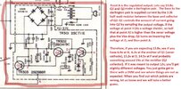
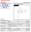
So to help you, the Bridge itself is called ID as S5VB/10 - it's a 4 diode (Full wave) Bridge rectifier rated 5A at 100PIV - but it has a catch.

The Diode package is (or should be) bolted to the side of the power supply unit - which should also be shared by the main output pass regulation transistor a PNP set up much like Unidens' / Galaxy - AM Regulator Pass transistor arrangement.

The Diodes themselves being rated at 100PIV - are DERATED when the system gets hot - so the PIV can drop by as much as 50% - making them more like 50PIV when the system is under heavy 4A draw in SSB modes and it's not getting cooled by forced air - it normally shouldn't need it but if the system has been getting poked by spikes from the AC side - that transformer just passes along the spike in ratio with the rest of the AC - so noise and spikes also take their toll on the system - so heat and a poorly regulated AC supply from your local power company is not helping the age factor the supply is facing.

1645794718953.png
 
Last edited:
  • Like
Reactions: RichardHartman
just wanted to jump in here to make sure you are both on the same page.

Richard, Andy is asking you to disconnect the power supply output positive wire from where it goes to the power switch, and the negative wire from where it connects to the main PC board.

that way you are just measuring the power supply output with nothing connected to it.
this way, if the power supply now reads 13.8 volts, you will know that your issue is on the main PC board.

if the power supply still reads 11 volts, you know the problem is the power supply itself.
LC
Thank you Handy Andy and Loose Cannon,
I will check this out tomorrow and will report.
 
  • Like
Reactions: Handy Andy
PS.jpg
I should have waited for a response to the other suggestions before posting this as I do believe the rectifier is a good candidate. Definitely start there!

I just have two random thoughts though. It was recapped 2 months ago. Was C302 put in backwards by chance? It kinda fits the failure timeline... The other though I had was that disconnecting the PS from the radio to see if the voltage comes up is not necessarily a solid indication that the problem lies beyond the PS. Transistors don't always fail as shorts. It could be that the pass transistor Q3 in the regulator circuit has an open collector and Q2 is now acting as the pass transistor. I know, there would need to be a reason for Q3 to blow, likely a short on the main board, or old age, but it was said it did TX on the insufficient voltage, so... I can assume the final and AM regulator are functioning (right?), therefore I'm going with old age. If this were the case, Q3's old age, the voltage would still come up to the expected value as the load is removed ~ giving the illusion that the short is on the main board. If Q3 does turn out to have an open collector, Q2 will simply cause the circuit to act like a really wimpy regulated supply (like it seems to be behaving now).

Again, I should have waited for the results of the other suggestions to come in as this just clutters up the conversation, but I hate using the delete button, so, you're stuck with my inexperienced thoughts, lol.
 
Last edited:
  • Like
Reactions: RichardHartman
Learned the hard way to simply replace every electrolytic cap, and then test EVERY semiconductor device in a power supply like this one. Choosing who to blame with voltage measurements can be iffy. A zener diode or transistor that flunks a test just gets changed.

This one does not have a trimpot for adjusting the output voltage. Those are always suspect when they get old. A drop of cleaner often smooths them out.

Testing every semiconductor device also serves to prevent fratricide. Changing just one failed part sounds reasonable, unless another failed part that you didn't replace overloads the new part and blows it out. Testing them all circumvents the risk of damaging a newly-installed component that way.

73
View attachment 57621
I should have waited for a response to the other suggestions before posting this as I do believe the rectifier is a good candidate. Definitely start there!

I just have two random thoughts though. It was recapped 2 months ago. Was C302 put in backwards by chance? It kinda fits the failure timeline... The other though I had was that disconnecting the PS from the radio to see if the voltage comes up is not necessarily a solid indication that the problem lies beyond the PS. Transistors don't always fail as shorts. It could be that the pass transistor Q3 in the regulator circuit has an open collector and Q2 is now acting as the pass transistor. I know, there would need to be a reason for Q3 to blow, likely a short on the main board, or old age, but it was said it did TX on the insufficient voltage, so... I can assume the final and AM regulator are functioning (right?), therefore I'm going with old age. If this were the case, Q3's old age, the voltage would still come up to the expected value as the load is removed ~ giving the illusion that the short is on the main board. If Q3 does turn out to have an open collector, Q2 will simply cause the circuit to act like a really wimpy regulated supply (like it seems to be behaving now).

Again, I should have waited for the results of the other suggestions to come in as this just clutters up the conversation, but I hate using the delete button, so, you're stuck with my inexperienced thoughts, lol.
OK,
So I began by removing the fuse and plugging in a 12v external supply. Unit did not turn on? Looked on back and had to move the switch to 12v, Boy o boy can you tell Im a rookie! So anyway unit still didn't turn on? Put the fuse back in line and it turned on, Now to the power supply...I checked the voltages like Brandon suggested, hmmm all correct?? So now I disconnect the external 12v and flip the switch back to 120v and the power supply is working correctly supplying 13.9v and minimal drop while tx.

So do you guys think that maybe the 120/12v switch might have had a bad contact? Talked on it for two days AM and SSB left it plugged in for the same time. Still holding steady at 13.9v

Thoughts?

73

Richard
 
  • Like
Reactions: brandon7861

dxChat
Help Users
  • No one is chatting at the moment.