I submit the following fodder:
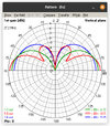
View attachment 60035
I wonder what would happen if I modeled this, it looks similar to a 4nec2 model with information added...

Well, it appeared to have been a 4nec2 model but its not. Under closer inspection it appears to have been drawn in some photo editing program.
Anyway, I matched the colors up for ease of reference. The pic shows the 1/4 wavelength antenna at 5.2 dBi, while my models shows it at 5.15 dBi, not bad, so far pretty close. Their half wavelength is shown to be 6 dBi gain, while mine is 6.72 dBi? What are they short changing the half wavelength antenna? And the 5/8 wavelength model isn't much better, their is 6.6 dBi gain while mine is 8.01 dBi gain, again not even close.
Now I have to ask, did they just get lucky with the 1/4 wavelength gain?
So which of these is correct? The correct answer is neither. The problem with this model, and the diagram above, is they both assume a perfect ground, and if your not a boat floating on the ocean, you don't have anything even like perfect ground under your antenna. These are optimal readings that only exist in an optimal if not "perfect" scenario, lab conditions if you will, and most people will never see in their life. As these numbers simply do not translate to the real world, thus they are not relevant.
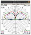
So lets see about making these numbers more relevant. Here I am taking the same antennas and putting them over average ground. Essentially changing one (ok, technically two) variable. The only difference from my model above and and my model below is the quality of the earth.

Wow, what a difference. The half wavelength here completely destroys everything else, and is in this case the only antenna with a positive gain. I wouldn't call this a simulation of reality, but it is one step closer than the models I made above. One simple change to make the results closer to reality and boom, drastic changes in some of the results. The hard question comes now, if I were to take this further, which reality should I try and simulate? My house? Your house? The antenna setup I see down the street? From experience I can tell you that in some cases, the 5/8 will outperform the 1/2, and in others the 1/2 will outperform the 5/8. It all depends on the variables, many of which most people who work with antennas don't even realize exists. Just one, for example, poor ground, good ground, are you near a lake? an ocean? And that isn't even considering other more well known things like height, which has the effect of bringing the outputs of the various antennas closer and closer together.
I can go on here, but I think I have demonstrated that a set of models, if they are even proper models, that exist with one specific set of variables, or even just made up on the spot as the image above appears to be, cannot be used as a general fact that applies to every antenna installation everywhere.
In essence, when it comes to antennas, the simpler something is to understand, the less likely it is to be true.
Based on 100 watt radio transmitted power.
I. At .5 wavelength (17.5481 feet) gain should be 13.15 dBi = 1259.378 watts ERP. with a radiation angle of 24 degrees.
II. At 1 wavelength (35.0962 feet) gain should be 14.62 dBi = 1766.673 watts ERP and a radiation angle of 15 degrees.
III. At 1.5 wavelength (52.6443 feet) gain should be 15.12 dBi = 1982.240 watts ERP and a radiation angle of 9 degrees.
IV. At 2 wavelengths (70.1924 feet) gain should be 15.09 dBi = 1968.594 watts ERP and a radiation angle of 6 degrees.
Note of importance is the diminished gain and ERP as antenna height moves higher than 1.5λ.
500W 10.64dBi ERP 3532
EIRP 5793
Footnote 07.30.22 The calculations above were based on, if I recall correctly, a Imax 2000 DBi of 12.5; your results may vary based on wishful thinking or real world fact. Advertised DBi is all I can go on; that and reeducation. Thanks DB for your attendance.
I don't think we actually disagree over the general idea you are trying to put forth but...
So this is the actual advertised gain claims for the Imax? Wow, who the hell needs a 7 or 8 element yagi with the Imax around...
I know you are trying, but... A real world Imax isn't going to get anything like those gain figures. Could it be made to happen in a lab environment? Possibly, but even if it can, is that even relevant?
I know what you are saying here, and I never once disagreed with the idea that you are presenting, but these numbers...
To my amazement I read of the huge increases related to the values of Db gain.
Simply said a 10DBi gain is a 10-fold gain and jumps amazingly to 20-fold a mere 3DBi higher (13DBi). Nawh, I sez to myself, Shirley that is a lie.
Nope, not a lie. 3 dB gain is very close to doubling the reference figure. 10 dB gain is very close to a 10 fold gain in power. So 13 dB, you do the 10 dB first, which is a 10 fold increase, then you do the 3 dB which doubles the previous result for a 20 fold increase in power. Or you can do it the other way, the 3 dB first and the 10 dB second, same result.
Decibels are not linear, and should not be treated as such. They are actually logarithmic in nature, which is another way of saying an exponential scale. Where you add the dB's directly, you multiply the underlying values. Its a way of representing sometimes very large ratios with much smaller numbers. It is a system that definitely has its quirks, but if you take the time to learn those quirks, it is a very intuitive system.
The DB
Last edited by a moderator:

