You are using an out of date browser. It may not display this or other websites correctly.
You should upgrade or use an alternative browser.
You should upgrade or use an alternative browser.
-
You can now help support WorldwideDX when you shop on Amazon at no additional cost to you! Simply follow this Shop on Amazon link first and a portion of any purchase is sent to WorldwideDX to help with site costs.
-
A Winner has been selected for the 2025 Radioddity Cyber Monday giveaway! Click Here to see who won!
Scrap pile GMRS Topfkreis
- Thread starter rixdafix
- Start date
Last edited:
Is this part of a topfkreis (pot circle/cavity filter) or a topfantenne (radiating element)?
Do you have English documentation (and can you share it)?
Do you have English documentation (and can you share it)?
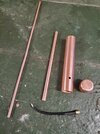
Antenna. I stumbled onto the design looking at J-poles and was intrigued. Internet search of topfkreis antenna shows a few results.
Found some with pictures, thanks!
I am curious whether the u part of the J-pole is rotated around the radiator axis forming a sleeve balun that doubles as a matching network or if that was done to correct the small asymmetry caused by the matching section of a typical J-pole (or both?). I guess I have some reading to do. Very interesting!
I am curious whether the u part of the J-pole is rotated around the radiator axis forming a sleeve balun that doubles as a matching network or if that was done to correct the small asymmetry caused by the matching section of a typical J-pole (or both?). I guess I have some reading to do. Very interesting!
Not sure about any of that as I'm very new to this but it appears the inner diameter of the (1/4 wave) outer tube (D) to the outer diameter of the (3/4 wave overall) inner tube (d) should be as close to 50 ohms as possible calculated the same as coax cable. Only info I can find shows formula 138log D/d. I think it should read 138log (D/d). Some calculators don't seem to care and others show two different results. With 1.00" ID outer tube and .375" OD inner tube, 138log (D/d) gives me 58.78 ohms which I assume is close enough to correct with feedpoint adjustment. I think. Only feedpoint calculation I found was x=14/f for a 440mhz version. No idea where the 14 came from but I ended up at around 30mm. No bueno. Another build shows 90mm. I shall also assume this is dependent on tube size. Please everyone forgive my ignorance on the topic and my crude builds, I'm learning. Future purchases include an ARRL antenna book and a 24" steel rule with at least 1/32 graduations Roger? I welcome any criticism and or suggestions. P.S. my Moxon kicks butt.Found some with pictures, thanks!
I am curious whether the u part of the J-pole is rotated around the radiator axis forming a sleeve balun that doubles as a matching network or if that was done to correct the small asymmetry caused by the matching section of a typical J-pole (or both?). I guess I have some reading to do. Very interesting!
Last edited:
The characteristic impedance of the 1/4λ section is something I was wondering about too, but I question whether 50Ω is where that should be.
Had some stuff typed up here but removed it after questioning myself (common occurrence). I need to go do some math.
Correction: Part of what I deleted treated the matching section like two parts, an inductive lower section and a capacitive upper section. This was in error because the antenna is not connected to the feed point with those components, rather, it is connected at the end of the capacitive section. When the overall matching section is 1/4λ, the inductive and capacitive reactances cancel regardless of where the tap point is meaning that section should not be treated as lumped elements and should be viewed as a transmission line instead. However, I do believe the part where I mentioned how the balun diameter affects bandwidth is still true.
Last edited:
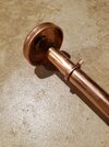
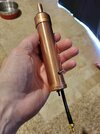
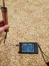
Appears in this configuration I actually built a Sperrtopf antenna. Difference being Sperrtopf is fed through bottom, (easier to experiment) where as Topfkreis feeds through side (get it right the first time). It's working really well.
dxChat
- No one is chatting at the moment.
-
-
-
-
@ boniface95:Hi there, I just posted this question, if anyone has time to check it out, i'd really appreciate some feedback. https://www.worldwidedx.com/threads...-radio-transmitters-in-the-same-space.270736/
-
dxBot:Kangsteri has left the room.

