• You can now help support WorldwideDX when you shop on Amazon at no additional cost to you! Simply follow this Shop on Amazon link first and a portion of any purchase is sent to WorldwideDX to help with site costs.
  • Click here to find out how to win free radios from Retevis!

Shure 577C wiring help please

H1driver

Supporting Member
Feb 13, 2011
145
192
53
I have a NOS Shure 577C that I am trying to wire for a 4 pin Cobra/Galaxy and have ran out of hair to pull out. So far the closest I have gotten is the following:

1-black, 2-green and black, 3-white, 4-red. This will key the radio but there is no audio.

1-black, 2-green, 3-white and black, 4-red. This keys the radio when plugged in w/o pressing ptt and still no audio.

1-black, 2-green, 3-white, 4-red. This does nothing plugged in radio, however when plugged in my mic tester it will key and has audio with a squeal (like when a power mic is turned up too much). Again does nothing connected to the radio.

Thanks in advance for any help.

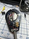
225F02F5-A412-4485-AE62-1C3334598778.jpegC7BDFC12-F4DD-4696-AC1C-D2BC4A8F8218.jpeg
 

I cannot find a whole lot but it looks like the innards of the mic need to be rewired. It's hard to tell by the photo as to what wires are coming in and what goes to the element. Also what wires are soldered to the reed switch.
 
I have a NOS Shure 577C that I am trying to wire for a 4 pin Cobra/Galaxy and have ran out of hair to pull out. So far the closest I have gotten is the following:

1-black, 2-green and black, 3-white, 4-red. This will key the radio but there is no audio.

1-black, 2-green, 3-white and black, 4-red. This keys the radio when plugged in w/o pressing ptt and still no audio.

1-black, 2-green, 3-white, 4-red. This does nothing plugged in radio, however when plugged in my mic tester it will key and has audio with a squeal (like when a power mic is turned up too much). Again does nothing connected to the radio.

Thanks in advance for any help.

View attachment 67697View attachment 67698
Check this Shure Mic Wiring Guide out...
 

Attachments

  • shure_issue_3_mic_wiring (5).pdf
    3.6 MB · Views: 5
  • Like
Reactions: H1driver
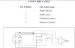
Ok after studying the switch, it will need to be rewired. You can do without the number 4 pin if it isn't a Cobra. This below is what we need to achieve to get the proper switching and if it were me I'd use the mic cord wire colors closer to the standard configuration like most others use but that's just my own opinion.
Screenshot_20240219_203328_Chrome.jpg
 
  • Like
Reactions: H1driver
Just to clarify the radio I am using for testing is a Galaxy.

Also:
1st reed on right- Red wire from the element.
2nd reed from right- Red wire from cord.
3rd reed from right- Green wire from cord.
4th reed from right- White wire from cord.

Black wire from cord goes to the element.
 
Let's kick this thread back open.

So I thought I had this wiring figured out but no dice. Can anyone help shed some light on the wiring for the standard 4 pin? I don't think I've fought one that I couldn't get figured out until this one.
Screenshot_20240407_210828_Drive.jpg

Any help is greatly appreciated.
 
Let's kick this thread back open.

So I thought I had this wiring figured out but no dice. Can anyone help shed some light on the wiring for the standard 4 pin? I don't think I've fought one that I couldn't get figured out until this one.
View attachment 68245

Any help is greatly appreciated.
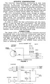
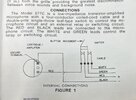
According to that diagram that particular mic is designed for relay switching.
Some electronically switched radios require the RX line to be connected to ground during receive. I was going to say all, but I'm sure there's exceptions. Since the switch contacts in this mic aren't connected at all during receive, there's no way to make that connection to ground for the RX line.

Again, I'm going by the diagram, I don't have one of these to confirm or deny that it works that way.

Making it work with an electronically switched radio isn't an impossible task, but it's going to take some imagination and a little bit of "engineering." I'm thinking it could be done with an inline relay circuit. Relay common to the mic black wire which also passes through to the radio as ground or common, radio RX wire to the normally closed contact, and radio TX wire to the normally open contact. Audio (mic red wire) passes straight through without touching the relay since it's switched in the mic anyways. Then just have the green and white mic wires inline with the power to the relay coil so that it turns on when you hit the PTT switch. The challenge if you chose to do this would be what to use as a power source for the relay. Oh, and don't forget the diode across the relay coil contacts to block back EMF spikes when the coil is de-energized. I don't think it would generate enough juice to fry anything, but better safe than stupid.

It could probably also be done with a transistor circuit, but I'm too lazy to figure that out.
 
  • Like
Reactions: Eldorado828
According to that diagram that particular mic is designed for relay switching.
Just the first obstacle. Any radio that receives without a mike plugged in should key up okay with this mike.

And like the man said, a radio that needs the mike to get receive audio isn't compatible with this mike.

But wait, there's more. This mike cartridge contains a one-transistor preamp circuit. It's purpose is for the mike cartridge to mimic a carbon-button mike. This is what land-mobile radios used when they first hit the market after WW2. Requires a source of current. When your voice audio causes the resistance of the element to change, this produces your audio voltage. And a lot of it, compared to the dynamic mike cartridge a CB used for years. A mike cartridge with a lot of output voltage could save the designer one whole tube section in the radio's design.

Motorola got tired of the problems that carbon mikes tend to have, and integrated a dynamic cartridge with a 1-transistor preamp. The preamp is powered the same way the carbon button was, with DC power coming down the mike cord's audio wire, and audio coming back down. A capacitor separates the audio from the DC inside the radio.

But that's why that one diagram shows a battery. We strapped a 9-Volt battery to the rear of a Motorola-brand mike like this and it was clumsy, but sounded pretty good. Later I added a couple of resistors and a capacitor inside my bench radio to feed power and separate the audio. Sounded pretty good on our Saturn Turbo.

But those are the two barriers on this one. Coming up with a receive side and a source of DC power to activate the mike cartridge and get audio out of it.

73
 
  • Like
Reactions: Eldorado828

dxChat
Help Users
  • No one is chatting at the moment.
  • @ Mark Malcomb:
    Hello BJ. Been a long time since I've been on. You doing well? Mark Malcomb
  • @ Naysayer:
    I’m
  • @ kingmudduck:
    Hello to all I have a cobra 138xlr, Looking for the number display for it. try a 4233 and it did not work