• You can now help support WorldwideDX when you shop on Amazon at no additional cost to you! Simply follow this Shop on Amazon link first and a portion of any purchase is sent to WorldwideDX to help with site costs.
  • Click here to find out how to win free radios from Retevis!

TRAM D201A adjustment points? Alignment question

Crambone

Well-Known Member
Jan 22, 2019
516
160
53
56
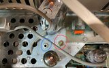
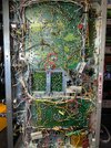
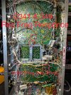
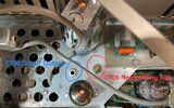
Ok, I picked a D201A and it had some funky stuff going on but after replacing a crystal, 3 trimmers and the meter IC it’s working but LSB & SSB are low power compared to AM. I want to do the Neutralization but the procedure mentions a T700 tuned for max DC (where is T700 and at what point is dc being measured) Also it says to adjust C706 (where is C706).
man is it me or are half of the Allignment produces wrong/ crystal labeled wrong in book?
Does anyone have a good neutralization procedure written they may care to share.
I included 2 pics with 5 adjustments I can’t even find reference too, I circled the adjustments????
 

Attachments

  • IMG_2920.jpeg
    IMG_2920.jpeg
    1 MB · Views: 12
  • IMG_2921.jpeg
    IMG_2921.jpeg
    1.4 MB · Views: 15

Ok, I picked a D201A and it had some funky stuff going on but after replacing a crystal, 3 trimmers and the meter IC it’s working but LSB & SSB are low power compared to AM. I want to do the Neutralization but the procedure mentions a T700 tuned for max DC (where is T700 and at what point is dc being measured) Also it says to adjust C706 (where is C706).
man is it me or are half of the Allignment produces wrong/ crystal labeled wrong in book?
Does anyone have a good neutralization procedure written they may care to share.
I included 2 pics with 5 adjustments I can’t even find reference too, I circled the adjustments????
 

Attachments

  • IMG_2921.jpeg
    IMG_2921.jpeg
    1.4 MB · Views: 6
  • IMG_2920.jpeg
    IMG_2920.jpeg
    1.1 MB · Views: 6
Now is not a good time to write this up in complete detail, but there are only two ways I know to actually neutralize a D201. Either by gum and by gosh, or using the "Collins" method by watching the final's grid current. The owner's manual procedure is nonsense.

Trickiest part is that C706 and T700 will interact. Change the setting of one, and now the other has been thrown off.

The by-gum-and-by-gosh method tweaks C706 until the final stops oscillating on SSB with no mike audio, then immediately re-peaking T700 for max modulated peak power on AM. Back and forth.

The Collins method watches the grid current of the final. Grid current should peak at the same spot on the Plate Tune as max output power. A 'scope probe where R709 meets R710 will show a negative DC voltage rise in proportion to rising grid current. Setting C706 so that this negative "grid leak" voltage peaks when the wattmeter peaks sounds easy, and you may have to settle for "close", rather than "exact" for this. Just don't forget to re-peak T700 every time C706 gets touched.

Just don't mistake bad carrier-balance adjustment from the sideband modulator for an oscillating final tube.

73
Thanks Nomad! Ya the 201A manual and most of the Allignment procedures are for squat, take into account all the miss labeled parts and it can get someone in a heap of trouble! I always say, ask, learn before touch. I appreciate the info
 
That procedure in the manual to neutralize is a joke, Nomad's method is the best,
BTW Mr, Nomad, In our talk on the phone on 3/26/24, I told ya about my D-201 putting out a carrier on SSB, I ran through the by-gum-and-by-gosh method and i got USB to stop throwing a carrier, But no luck on LSB, Well i took a chance and i swapped out the BM board and that was it. I had replaced all the electrolyte cap's in the one board, But this board i put in was one from Fixr, so just keep that in mind if some one else has the problem to try another BM board.
 
Best clue for a "carrier" on sideband transmit is a frequency counter inline with the radio's coax. If your sideband carrier is stable, and on the channel frequency the fault is probably with the balanced modulator board. If the frequency is unstable, and not really near the selected channel frequency, this is probably the final stage oscillating at its own random frequency.

73
 

dxChat
Help Users
  • No one is chatting at the moment.
  • @ BJ radionut:
    EVAN/Crawdad :love: ...runna pile-up on 6m SSB(y) W4AXW in the air
    +1
  • @ Crawdad:
    One of the few times my tiny station gets heard on 6m!:D
  • @ Galanary:
    anyone out here familiar with the Icom IC-7300 mods
  • @ Crawdad:
    7300 very nice radio, what's to hack?
  • @ kopcicle:
    The mobile version of this site just pisses me off