• You can now help support WorldwideDX when you shop on Amazon at no additional cost to you! Simply follow this Shop on Amazon link first and a portion of any purchase is sent to WorldwideDX to help with site costs.
  • Click here to find out how to win free radios from Retevis!

TRC-449 repair

TM86

Supporting Member
I Support WorldwideDX.com!
Jul 6, 2014
1,883
2,962
273
Payson, AZ
TRC-449 that came from a smoker's home. I've had it for a while, but had to literally soak the covers in Fabreeze and leave it in the garage for a few weeks to let the smell dissipate to the point I could be in the same room with it. It's been recapped and deglued. Found at least 5 leaky caps and one jumper that the glue was happily dissolving. That's all been addressed and no animals were harmed in the process.

Now I've hit actual problem number 1. On/off switch on the volume pot is dead. I know it's dead because I can bypass it at the terminals and get power to the rest of the radio. This is a small 10K pot with an spst switch made by ALPS originally. Since I know I can't be the first person to see this in the 40+ year history of these radios, I'm wondering what is usually substituted in for a replacement?

FWIW, there is a "76Q-10KA" number printed on the pot itself, but so far my searches for that have been at best unhelpful.
Does it "click" when turning on or off?
 

Audio (Log) taper.

"76Q-10KA" - the "A" indicates an Audio or Logarithmic taper. "B" would be a Linear taper.
 
Dang, you guys are fast!

Woody - yes, it does "click" when rotated all the way to the left. It just doesn't make an electrical connection. I did get it to kind of work once, but there was only about 7 or 8 volts coming out of it. Bypassing it gave the full 13.8 volts. So there appears to be something going on with the switch contacts.

Shadetree - composing email to Ken now.

sp5it and Dr_DX - I thought it was probably an audio taper being the volume knob. Thanks for the confirmation.
 
  • Like
Reactions: Shadetree Mechanic
You might be able to carefully open it up by bending the tabs that hold the metal can on the back. Sounds like all it needs is the switch contacts cleaned.
I could try hosing it down with Deoxit. Whether I do that or replace it I have to pull it out of the front panel anyways. Hard to get the straw in where it sits without spraying a bunch of other stuff I'd rather not have the oil get on.
 
  • Like
Reactions: Shadetree Mechanic
Got the pot out of the front panel and hit it with the Deoxit. And turned the paper towel underneath it black. The more I rotated the pot, the more crud came out.

I had to go do something else for a few hours, but when I came back I hit it with the Deoxit again. More crud. Kept going until the crud was down by at least half. Plugged the radio in and the power switch now works every time. Will have to see if that's still true tomorrow morning.

If the Deoxit "fix" holds I can start figuring out whether or not the PLL is dead. Now that I can keep the power on I've found I have no transmit or receive.

But it's one step closer to working.
 
  • Like
Reactions: Shadetree Mechanic
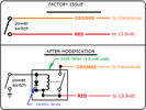
The power On-Off switch in the 858 PLL rigs is a common failure point. The tiny contacts in the factory switch just can't handle the higher current when these radios are tuned to the max. I always use a relay to switch the DC on and off. I use the original power switch to operate the relay.

- 399

View attachment 67680
Any recommendations on a particular relay? I've located a few possibilities, but if you've got a favorite for this application I'd like to at least take a look at the specs on the beast.
 
I like junk yard relays. They are free and getting smaller with every newer vehicle that is hauled in.

Not to hijack the thread, just saw an opportunity to improve on 399's relay mod and show a trick to keep them cool.

Take a relay out of a 2005 buick lasabre. Its an Omron 8567 4-terminal relay. I don't know the coil voltage on these newer computer cars, but I do know that bugger gets hot connected to 13.8v. So, here is how to drive a relay without making it hot.

Step 1, Ohm relay coil
[Omron coil measured 94Ω]
Step 2, set power supply to 13.8v and measure latching current
[Omron pulls 144mA @ 13.8v]
Step 3, reduce voltage until it drops out
[Omron relay drops out at 3.2v]
Step 3, divide that voltage by the resistance measured in step 1
[Omron minimum holding current is 3.2/94=34mA]
Step 4, round that current up to 40mA for good measure
Step 5, calculate coil voltage at 40mA
[.040A x 94Ω = 3.76v]
Step 7, Calculate voltage across dropping resistor
[13.8 - 3.76 = 10.04v]
Step 8, calculate dropping resistor value
[ 10.04v / .040A = 251Ω]
Final Step. Determine rating of dropping resistor
[10.04v x .040A = 0.4016w

This particular relay may have been intended to be driven with 5v, but if you limit the holding current, it won't matter what you took the relay from. In the Omron case, four 1/4w 1k resistors in parallel will have twice the dissipation rating, provide the proper resistanec, and will hold up for a long time. Overall, with this relay, you will be pulling 41mA through the switch instead of the 144mA with just the relay coil across 13.8v.

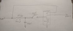
The capacitor provides the initial latching current and the resistor supplies the holding current. Note the location of the switch after the resistor/cap so the cap is charged before the switch is thrown.
IMG_20240218_160523404.jpg
Forgot to add the diode, but you get the idea...

Worded a different way, you are making a voltage divider that puts the bare minimum reliable holding voltage across the coil and using the capacitor to supply the initial higher latching voltage.
 
Last edited:
Not to hijack the thread, just saw an opportunity to improve on 399's relay mod and show a trick to keep them cool.
No worries, it's not like I've never derailed a thread before. Usually accidentally. But at least you put up something interesting and related.

Back on track, I've checked my voltages in RX. Thought I had a problem with the 8.80V (test point 3 in the Sam's for those playing at home) supply, but it turns out that as long as the PLL is out of lock that voltage gets cut off by TR29.

You can probably guess from that bit of info that my PLL is out of lock. VCO appears to doing it's thing, and I've got outputs from the PLL chip itself. They just don't seem to be working together. I'm seeing somewhere around 2.5 MHz for all channels on Pin 11 of the PLL, where I should be seeing somewhere between 0.91 and 1.35 MHz. As best I can tell, this radio does not appear to have ever been modified. Worked on, maybe, but not modified.

So I'm off to pull the shield over the VCO section of the board and see if I can find any broken, or just bad, solder joints. It's quite possible that this is self-induced from the recap job. If I can't find anything I'll probably whine about it here.
 
Any recommendations on a particular relay? I've located a few possibilities, but if you've got a favorite for this application I'd like to at least take a look at the specs on the beast.
TM86 -

I use a lot of relays, so I buy them in bulk. 15 relays for 15 bucks from Amazon ($1.00 ea) Approx 1/2" x 1" so they'll fix anywhere. Brandon's circuit is nice, but he omitted the diode across the relay coil to absorb the inductive spike when the relay unkeys. The attachment shows the relays I use, but you can get similar ones at any electronic parts place. Good luck.73.

- 39912v relay.png
 

dxChat
Help Users
  • No one is chatting at the moment.
  • dxBot:
    Greg T has left the room.
  • @ BJ radionut:
    EVAN/Crawdad :love: ...runna pile-up on 6m SSB(y) W4AXW in the air
    +1
  • @ Crawdad:
    One of the few times my tiny station gets heard on 6m!:D
  • @ Galanary:
    anyone out here familiar with the Icom IC-7300 mods