Just thought I would share this simple two tone roger beep circuit I built and decided to rig into an old radio of mine.
It works perfectly and produces two tones, first one higher in pitch than the other.
I know some people have strong feelings against roger beeps and other noise toys but this was just a "for fun" project to see how well it would work using a circuit I whipped up.
The tones are a clean sine-wave so they sound pleasant and should be at talk level so not to annoy the hell out of others. The idea after all is to let them know you are done talking, not to blast their speaker with a BEEP BEEP :glare:
This was while in the test phase wired into the mic jack and into the power source before hardwiring it in my radio..

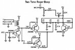
Schematic. Sorry if it is hard to read but I have not had the time to use Diag to draw it out yet on the computer..

Transistors are either 2N3904 or 2N3906. the 4.7 is actually 4.7K. I forgot to draw the K lol.
Relay I used was a 5 volt type and timing relies on 5 volts specific so a single 7805 regulator is necessary.
The dotted line is either optionally a switch to flip between single tone roger or two tone. I wired mine w/o the switch so two tone is forced.
Playing with the two timer transistors resistor values in the center of the schematic will change the note.
The 2.2uF cap on the PTT button will change the duration of the beeps. Higher value = longer beep(s).
If you put a switch in series with the 2.2uF cap you can easily switch between roger beep on/off.
You could add on additional transistor stages (like the bottom transistor with two connections) to add more tones for 3+ tones but what is the point besides annoying others?
Just figured the info would be valuable to experimenters.
I build my stuff on perfboard. Watch out when grounding roger beep boards directly to the chassis since many radios have a separate RF ground and electrical ground.
If anyone uses this idea please give credit where due.
It works perfectly and produces two tones, first one higher in pitch than the other.
I know some people have strong feelings against roger beeps and other noise toys but this was just a "for fun" project to see how well it would work using a circuit I whipped up.
The tones are a clean sine-wave so they sound pleasant and should be at talk level so not to annoy the hell out of others. The idea after all is to let them know you are done talking, not to blast their speaker with a BEEP BEEP :glare:
This was while in the test phase wired into the mic jack and into the power source before hardwiring it in my radio..

Schematic. Sorry if it is hard to read but I have not had the time to use Diag to draw it out yet on the computer..

Transistors are either 2N3904 or 2N3906. the 4.7 is actually 4.7K. I forgot to draw the K lol.
Relay I used was a 5 volt type and timing relies on 5 volts specific so a single 7805 regulator is necessary.
The dotted line is either optionally a switch to flip between single tone roger or two tone. I wired mine w/o the switch so two tone is forced.
Playing with the two timer transistors resistor values in the center of the schematic will change the note.
The 2.2uF cap on the PTT button will change the duration of the beeps. Higher value = longer beep(s).
If you put a switch in series with the 2.2uF cap you can easily switch between roger beep on/off.
You could add on additional transistor stages (like the bottom transistor with two connections) to add more tones for 3+ tones but what is the point besides annoying others?
Just figured the info would be valuable to experimenters.
I build my stuff on perfboard. Watch out when grounding roger beep boards directly to the chassis since many radios have a separate RF ground and electrical ground.
If anyone uses this idea please give credit where due.


