You are using an out of date browser. It may not display this or other websites correctly.
You should upgrade or use an alternative browser.
You should upgrade or use an alternative browser.
-
You can now help support WorldwideDX when you shop on Amazon at no additional cost to you! Simply follow this Shop on Amazon link first and a portion of any purchase is sent to WorldwideDX to help with site costs.
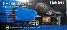
Uniden 505XL
- Thread starter KK4JW
- Start date
Shadetree Mechanic
Delaware Base Station 808
Shadetree Mechanic
Delaware Base Station 808
As a general thing, first find the spike diode. Should be easy to spot, just follow traces from the audio tranformer pins until one of them leads to the anode of a black epoxy 1-Amp rectifier diode. On the diode's other end is the cathode, the end with the band on it. The trace it feeds into is our modulated B+ that will power and modulate the driver and final transistors. Downstream from the diode you'll find a small-value electrolytic capacitor, almost always under 10uf with the positive end connected to the modulated B+ line, and the negative side connected to a diode. Remove the solder from one side of this capacitor to break the circuit and see if it affects the modulation limit. Good chance it will.
73
73
Not so different from cars or trucks made years apart. They never stop tweaking their manufacturing process, and the circuit board will change even though the model number stays the same.
73
73
Can't tell if your being funny or serious. This is a 40 dollar throw away radio new, 15 bucks used. It's probably dinky little surface mount parts, bump the modulation and run a better mic. Done.How about direct injectiin hifi audio mod for the 5
Hey, the desire to modify never goes away, even as the barriers to doing it get higher and higher. Besides, if I was going to risk screwing up a radio with a 'direct' mod, the cheaper the better.
73
73


