You are using an out of date browser. It may not display this or other websites correctly.
You should upgrade or use an alternative browser.
You should upgrade or use an alternative browser.
-
You can now help support WorldwideDX when you shop on Amazon at no additional cost to you! Simply follow this Shop on Amazon link first and a portion of any purchase is sent to WorldwideDX to help with site costs.
-
The Retevis Holidays giveaway winner has been selected! Check Here to see who won!
Uniden Washington no Rx
- Thread starter 1107
- Start date
Ok, you can hear a station when you touch D10...
Where is D10 in the schematic?

When looking at a schematic, it's not just the part number you're looking for...
IT's the parts that it connects to, as well as understand the purpose
the part has in being used in this radio - this particular way.
To keep this simpler, D10 is a one-way valve that helps TR13 discern signals it can process. When in the right mode (thru your mode switch) the diode conducts power - in doing so sends power into another diode - well why? It is supposed to allow one set of signals to get into and get amplified by TR13.
Locate the Trace on the Schematic for D10 goes to a resistor - then has a long run somewhere...let's see if we know where it goes...
You can do a continuity check - since it appears to head off somewhere, to help this further it heads off to a POLE used in the MODE switch. Switches can be stacked together to form a "gang" - which then uses the switches common shaft and knob - so that when lined up just right; turn, rotate - the shaft to move a set of contacts from one set to another set - all at the same time - but using the stacking method of ganging, allows these switches to serve a function of moving power thru the process of POLES - meaning separate and insulated, but move together in an axis - the shaft of the switch - to position contacts (Rotor) to the stationary ones on the outside of the switch (stator) that let you hook up wires to - using the MODE switch , we just have to understand the Mode switch's purpose.
The Mode then powers up the radios mode sections that if left on all the time - would cause problems. So, the mode switch turns on AM but turns off SSB side.
Then SSB can then turn on and AM side turns off when you want to hear SSB.
Both AM and SSB use TR13 - one though - is simple AM radio - a diode detector and the TR13 just amplifies it.
In SSB - you can use a function called Heterodyne - a means of mixing two signals - two types; one is a stationary fixed frequency with the other shifting around that frequency - allows you to get a third out of the other two thru the process of cancellation (a way of phasing signals to beat - then the remaining is an error between the two - or the error is the audio deviating one signals frequency around that fixed one. Your third)
So D10 let's you hear the "DJ" on the local stations but why are you not hearing the AM receiver - so we got this far, we have to find out why you don't have an IF signal the AM side of the radio - can produce to get it to TR13.
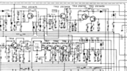
You'll need to use the snippet of the schematic and see if D10 is going into D11 but is D11 still a diode or is it blown open? A simple diode check on that same voltmeter can help - simply check both ways of your test leads on D11 with the power off.
Why would this matter? IF D11 is not working as in working like a diode - your effort to go into AM mode and just hear what the detector (output of R101 and C91 - from the AM ANL and Detector side) at TP 3 - is moot - won't work.
Same can be said for TP3 and Mode switch itself - if it can send power to the right sections to power them properly and turn off other sections that are not used - then a conflict occurs, and you still don't hear anything.
Where is D10 in the schematic?

When looking at a schematic, it's not just the part number you're looking for...
IT's the parts that it connects to, as well as understand the purpose
the part has in being used in this radio - this particular way.
To keep this simpler, D10 is a one-way valve that helps TR13 discern signals it can process. When in the right mode (thru your mode switch) the diode conducts power - in doing so sends power into another diode - well why? It is supposed to allow one set of signals to get into and get amplified by TR13.
Locate the Trace on the Schematic for D10 goes to a resistor - then has a long run somewhere...let's see if we know where it goes...
You can do a continuity check - since it appears to head off somewhere, to help this further it heads off to a POLE used in the MODE switch. Switches can be stacked together to form a "gang" - which then uses the switches common shaft and knob - so that when lined up just right; turn, rotate - the shaft to move a set of contacts from one set to another set - all at the same time - but using the stacking method of ganging, allows these switches to serve a function of moving power thru the process of POLES - meaning separate and insulated, but move together in an axis - the shaft of the switch - to position contacts (Rotor) to the stationary ones on the outside of the switch (stator) that let you hook up wires to - using the MODE switch , we just have to understand the Mode switch's purpose.
The Mode then powers up the radios mode sections that if left on all the time - would cause problems. So, the mode switch turns on AM but turns off SSB side.
Then SSB can then turn on and AM side turns off when you want to hear SSB.
Both AM and SSB use TR13 - one though - is simple AM radio - a diode detector and the TR13 just amplifies it.
In SSB - you can use a function called Heterodyne - a means of mixing two signals - two types; one is a stationary fixed frequency with the other shifting around that frequency - allows you to get a third out of the other two thru the process of cancellation (a way of phasing signals to beat - then the remaining is an error between the two - or the error is the audio deviating one signals frequency around that fixed one. Your third)
So D10 let's you hear the "DJ" on the local stations but why are you not hearing the AM receiver - so we got this far, we have to find out why you don't have an IF signal the AM side of the radio - can produce to get it to TR13.
You'll need to use the snippet of the schematic and see if D10 is going into D11 but is D11 still a diode or is it blown open? A simple diode check on that same voltmeter can help - simply check both ways of your test leads on D11 with the power off.
Why would this matter? IF D11 is not working as in working like a diode - your effort to go into AM mode and just hear what the detector (output of R101 and C91 - from the AM ANL and Detector side) at TP 3 - is moot - won't work.
Same can be said for TP3 and Mode switch itself - if it can send power to the right sections to power them properly and turn off other sections that are not used - then a conflict occurs, and you still don't hear anything.
I tend to get "enthusiastic" when it comes to radio - but also you said you have a "photofact" which is a great example.
Now, I know, I understand that it may not be for the radio you are working on - but applicable, just not directly, to what we've got on our hands,
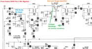
Here's one for a Cobra 2000 - different radio but has sections in it that work and operate in similar fashions as to what you have...

By example of a working radio, parts and layout with values; like voltages and signal tracing - which can offer you a way and means to develop several skills in tech repair that can be useful in any form of repair later. Because of what is known by how radio works, the concepts you work with can apply, to other radios - it is not that different.
You don't "earn degrees" in radio - you learn mostly by experience and hands-on learning - it takes experience, but you have got some great examples to start learning from. You just have to do the legwork. IT helps when you can have some electronics training but most of the engineering is left to the field work of those wishing to experiment.
There's a lot of users in this forum that work in similar jobs, right alongside you so you will be in good company.
Now, I know, I understand that it may not be for the radio you are working on - but applicable, just not directly, to what we've got on our hands,
Here's one for a Cobra 2000 - different radio but has sections in it that work and operate in similar fashions as to what you have...

By example of a working radio, parts and layout with values; like voltages and signal tracing - which can offer you a way and means to develop several skills in tech repair that can be useful in any form of repair later. Because of what is known by how radio works, the concepts you work with can apply, to other radios - it is not that different.
You don't "earn degrees" in radio - you learn mostly by experience and hands-on learning - it takes experience, but you have got some great examples to start learning from. You just have to do the legwork. IT helps when you can have some electronics training but most of the engineering is left to the field work of those wishing to experiment.
There's a lot of users in this forum that work in similar jobs, right alongside you so you will be in good company.

