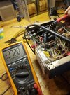
That is a brand new zener Shockwave that I installed right before the photo was taken and I haven't had a tube in the unit since I have been repairing it The resistor in question is supposed to be 22,000 ohms. At 23,000 ohms it's well within tolerance. I've also looked at another unit and it is the correct value. Your picture shows the only thing this resistor is feeding right now, is the diode with no other connections at that point and you were showing -5 volts at the junction between the resistor and the zener diode. The only way that's possible is if you have a 5 volt zener diode in that spot, or the 36 volt zener diode failed as a result of a tube short.
You are using an out of date browser. It may not display this or other websites correctly.
You should upgrade or use an alternative browser.
You should upgrade or use an alternative browser.
-
You can now help support WorldwideDX when you shop on Amazon at no additional cost to you! Simply follow this Shop on Amazon link first and a portion of any purchase is sent to WorldwideDX to help with site costs.
Wawasee JB150 issues "low bias"
- Thread starter Danzik
- Start date
He's right. I remembered it wrong.is supposed to be 22,000 ohms. At 23,000 ohms it's well within tolerance.
Happens.
73
Shouldn't that zener work though, as long as they gave me right ones, I can't hardly read the print on them even with a magnifying glassHe's right. I remembered it wrong.
Happens.
73
A working 36 volt zener will appear as an open circuit and only begins to conduct like a short, when you reach anything above 36 volts. Everything above 36 volts gets dropped across your 22 k resistor, while the regulated 36 volts remains across the diode. Since you've disconnected the brown wire feeding the bias circuit, we can easily eliminate all other variables in the circuit and strongly suspect that diode. Only seeing 5 volts across the diode, as the only conduction path, assures me it's the diode conducting way too early.Shouldn't that zener work though, as long as they gave me right ones, I can't hardly read the print on them even with a magnifying glass
It may have started life as a 36 volt zener. After a tube meltdown and likely internal tube arc, it's now acting like a 700 ohm resistor. These devices are fragile to overload and typically turn into low value resistors when they are overloaded.The zener I have installed was a 1N4753A perhaps this is not the right one ???? It was listed as a 1w 36v zener
I have replaced it since the JB-150 went down as the original one was bad, I have a pack of 10 of then and replaced it again before this post, same results, I ordered a different zener so I will try that next thanks for your help on this Shockwave, we'll see what happens when I get the other oneIt may have started life as a 36 volt zener. After a tube meltdown and likely internal tube arc, it's now acting like a 700 ohm resistor. These devices are fragile to overload and typically turn into low value resistors when they are overloaded.
If you can cut one side or lift one side of the zener and the voltage on the output of the 22k resistor approaches =150 volts, the zener is responsible for loading the resistor all the way down to =5 volts.I have replaced it since the JB-150 went down as the original one was bad, I have a pack of 10 of then and replaced it again before this post, same results, I ordered a different zener so I will try that next thanks for your help on this Shockwave, we'll see what happens when I get the other one
NOTE: While this test is safe to do in this amplifiers negative bias circuit, do not randomly test for shorted ones like this. Because, everything the zener feeds will be hit with the full unregulated voltage.
It's safe here for two reasons. It simply mimics the cutoff bias voltage that the circuit would see in receive and, the tube is not even installed.
Literally the only way it could not be the zener, is if we are missing another wire being connected to the junction of the 22k resistor and the zener diode. I've purchased a bag of 100 of them once, all defective, with no consistency.
Yes, I have had the zener removed previously and there was -150 on the resistor end, hopefully when that new zener comes in all will be goodThIf you can cut one side or lift one side of the zener and the voltage on the output of the 22k resistor approaches =150 volts, the zener is responsible for loading the resistor all the way down to =5 volts.
NOTE: While this test is safe to do in this amplifiers the negative bias circuit, do not randomly test for shorted ones like this. Because, everything the zener feeds will be hit with the full unregulated voltage.
It's safe here for two reasons. It simply mimics the cutoff bias voltage that the circuit would see in receive and, the tube is not even installed.
Literally the only way it could not be the zener, is if we are missing another wire being connected to the junction of the 22k resistor and the zener diode. I've purchased a bag of 100 of them once, all defective, with no consistency.
Indeed the zener was at fault, I got the new ones in and installed them and bingo, I have better negative bias however I am still noticing it trying to cherry the plate a bit in recieve mode I have -25 vdc in recieve and -37 vdc in transmit, is this backwards perhaps since it was once a recieve booster??? But all my other linears goes more negative on transmit. Fyi I am currently testing it with a 6L6 because I don't want to toast a 8417 in it till I test it well ! ThanksIf you can cut one side or lift one side of the zener and the voltage on the output of the 22k resistor approaches =150 volts, the zener is responsible for loading the resistor all the way down to =5 volts.
NOTE: While this test is safe to do in this amplifiers negative bias circuit, do not randomly test for shorted ones like this. Because, everything the zener feeds will be hit with the full unregulated voltage.
It's safe here for two reasons. It simply mimics the cutoff bias voltage that the circuit would see in receive and, the tube is not even installed.
Literally the only way it could not be the zener, is if we are missing another wire being connected to the junction of the 22k resistor and the zener diode. I've purchased a bag of 100 of them once, all defective, with no consistency.


We used the center pole of the relay to interrupt the screen-voltage supply to pin 4 on the big tube in receive mode. The setups that switch the grid bias higher for receive, lower for transmit just don't seem to be as stable.
At least shutting down the screen grid does a decisive job of turning off the tube.
73
At least shutting down the screen grid does a decisive job of turning off the tube.
73
I absolutely understand exactly what you are stating here Nomadradio and I may end up changing this box this way myself, as of right now the bias is backwards I think-25 on recieve and -35 on transmit and I actually have two boxes that are this way which was one reason I was getting confused, I think when people had these modulators before me they didn't get wired up correctly changing from a recieve booster to a amplifier I had to change alot on the relay to even make this one function. I also have one of the newer models with the seeker meter in it that has a fixed negative bias of -54 vdc, was thinking it was only a 2 pole relay though but could be wrong on that, I could use the center poles on this older one for the screen voltage and setup a fixed bias on this one I suppose. Thank you guys for your help on this it is appreciated!We used the center pole of the relay to interrupt the screen-voltage supply to pin 4 on the big tube in receive mode. The setups that switch the grid bias higher for receive, lower for transmit just don't seem to be as stable.
At least shutting down the screen grid does a decisive job of turning off the tube.
73
I worked on it a bit more tonight, I guess the deal is that these older JB150 don't like a 6L6 tube as much probably due to that screen grid voltage always being present " I run a 6L6 in the JB150 that has a seeker meter all the time but it's a better setup" I installed a 8417 tube back in the old 2 tuber and it seems to be behaving better anyways! I may modify these sometime though and try to set one up with a fixed bias and use the center tap on the relay for the screen grid perhaps  any suggestions would be appreciated thanks again
dxChat
- No one is chatting at the moment.

