• You can now help support WorldwideDX when you shop on Amazon at no additional cost to you! Simply follow this Shop on Amazon link first and a portion of any purchase is sent to WorldwideDX to help with site costs.
  • Click here to find out how to win free radios from Retevis!

Wawasee style JB12 " no bias components"

Danzik

Active Member
Oct 18, 2022
242
26
38
46
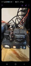
Hi there, I have this modulator that is alot like a JB12 that I am working on and recapping after opening the unit up I noticed that there is a pair of old camera batteries 22 1/2 volt that are being used for the negative bias LOL, I also noticed there is only 4 wires coming from the transformer and not 6 wires like the Wawasee's so with this being said is there any easy way around this can I come off from somewhere else to put my bias circuitry in safely? I find multiple places that have around 50 VAC but they are going other places. Thanks 20241015_211753.jpg
 

Hi there, I have this modulator that is alot like a JB12 that I am working on and recapping after opening the unit up I noticed that there is a pair of old camera batteries 22 1/2 volt that are being used for the negative bias LOL, I also noticed there is only 4 wires coming from the transformer and not 6 wires like the Wawasee's so with this being said is there any easy way around this can I come off from somewhere else to put my bias circuitry in safely? I find multiple places that have around 50 VAC but they are going other places. Thanks View attachment 70491
Why not add another small transformer?
 
  • Like
Reactions: Danzik
I think I may have found a wire cutoff at the base of the transformer, I added wire to it so I may have my issue resolved hopefully!
 
Hi there, I have this modulator that is alot like a JB12 that I am working on and recapping after opening the unit up I noticed that there is a pair of old camera batteries 22 1/2 volt that are being used for the negative bias LOL, I also noticed there is only 4 wires coming from the transformer and not 6 wires like the Wawasee's so with this being said is there any easy way around this can I come off from somewhere else to put my bias circuitry in safely? I find multiple places that have around 50 VAC but they are going other places. Thanks View attachment 70491
Unfortunately there appears to be more than one issue here. Many of these designs only used a two pole relay and offer no ability to switch the bias on and off. They are tube killer's from day one as a result.
 
  • Like
Reactions: Danzik
If that's my only route I can take I may have to do that but there isn't much room to add another, would probably have to replace the one that I in it.
I modified one for use with a 6LF6 tube that required more negative bias. I took a small 24 volt transformer out of a tiny "wall wart" and used a voltage doubler. This provides over -65 volts DC to work with. Usually enough to place a stock tube into cutoff. Although, I prefer switching the screen voltage off in RX on these units.
 
With any luck the relay has three poles.

We adopted the habit of leaving the negative grid bias fixed, and using the center section of the relay to shut off screen voltage to the tube in receive mode. Seems to do a better job of shutting down the tube than switching the grid bias.

73
 
  • Like
Reactions: Shockwave
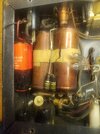
These amplifiers are a wonderful demonstration of how few parts are needed to make something work , as compared to how many more parts are required to make something work correctly. How many extra circuits can you count here, as compared to a stock unit ?
20241020_033054.jpg
20241020_033140.jpg
20241020_033025.jpg
 
  • Like
Reactions: Danzik
How many extra circuits can you count here, as compared to a stock unit ?
Um, one standard buttload, plus or minus 1 db.

And neutralized, no less. Trickier than it looks.

And variable drive level? Probably necessary. That tube shouldn't need more than about a whole Watt to drive it in a neutralized circuit. Wouldn't need a bachelor's degree to operate it, but it might help.

73
 
  • Like
Reactions: Shockwave
Um, one standard buttload, plus or minus 1 db.

And neutralized, no less. Trickier than it looks.

And variable drive level? Probably necessary. That tube shouldn't need more than about a whole Watt to drive it in a neutralized circuit. Wouldn't need a bachelor's degree to operate it, but it might help.

73
While I wasted a lot of time trying other methods of stabilizing this amplifier, the addition of neutralization only required adding two more parts. The air variable you see in the pictures and a 680 picofarad capacitor that was placed in series with the grounded side of the RF input transformers primary. That is the injection point from the air variable off of the plate circuit. RF entering that side of the primary winding, is 180° out of phase with the drive power.

Alignment was done with the amplifier off and its relay locked in the transmit position. Place a carrier on the input, monitor feed through RF voltage with a scope and dummy load on the output and adjust the neutralization capacitor for the deep null in RF voltage on the output.

Other things like adding a transistor buffered shunt screen regulator and a input variable that could handle at least 25 watts PEP while showing the radio under a 1.5 to 1 SWR at any setting, was a little more tricky.

One other thing I'll point out, has to do with that rule about not using inductive resistors for RF. How often have we seen a half watt 100 ohm variable burnt open on something like a Texas Star? I've found that some smaller rheostats actually work well here. Sometimes they need a little non-inductive padding around them to keep the SWR nice. That doesn't work if you need every drop of Drive power. However, if you have some to waste, you can improve the input SWR with padding.

Unfortunately there is no specific rheostat value I can recommend, since the construction of the device has more of an impact than its ohm rating. Ones that work well are typically between 15 and 25 ohms and physically small. Once the package gets larger, you are dealing with too much inductance.
 
Last edited:
  • Like
Reactions: Shadetree Mechanic
With any luck the relay has three poles.

We adopted the habit of leaving the negative grid bias fixed, and using the center section of the relay to shut off screen voltage to the tube in receive mode. Seems to do a better job of shutting down the tube than switching the grid bias.

73
I believe this one is just a 2 pole Nomad, but the real issue is that it doesn't have any negative bias at all and there is no 50 VAC line available from the transformer, I had found a cut off wire and thought I was in luck but it was a 210 VDC line
 
I believe this one is just a 2 pole Nomad, but the real issue is that it doesn't have any negative bias at all and there is no 50 VAC line available from the transformer, I had found a cut off wire and thought I was in luck but it was a 210 VDC line
Crack a 24 volt AC wall wart apart and pull out the tiny inch and a half transformer. Run that through two diodes and two capacitors to form a voltage doubler and walla, you've got 65 volts of DC to work with. The first picture in my post above, shows this transformer mounted on the deck.

I see the relay as being the bigger problem. I think it's coil is only 6 volts. I had to add a micro switch on top of my relay in order to provide a fourth pole to key another amplifier downstream.

While that might work in your application, finding a micro switch to handle the screen voltage may be difficult. Although, it might handle the input RF switching and free up one contact on the relay. At some point, it gets easier just to find another relay.
 
  • Like
Reactions: Danzik
Crack a 24 volt AC wall wart apart and pull out the tiny inch and a half transformer. Run that through two diodes and two capacitors to form a voltage doubler and walla, you've got 65 volts of DC to work with. The first picture in my post above, shows this transformer mounted on the deck.

I see the relay as being the bigger problem. I think it's coil is only 6 volts. I had to add a micro switch on top of my relay in order to provide a fourth pole to key another amplifier downstream.

While that might work in your application, finding a micro switch to handle the screen voltage may be difficult. Although, it might handle the input RF switching and free up one contact on the relay. At some point, it gets easier just to find another relay.
Yeah, I think this is the route I am going to take. Thanks for the advice Shockwave
 
  • Like
Reactions: Shockwave

dxChat
Help Users
  • No one is chatting at the moment.
  • @ BJ radionut:
    EVAN/Crawdad :love: ...runna pile-up on 6m SSB(y) W4AXW in the air
    +1
  • @ Crawdad:
    One of the few times my tiny station gets heard on 6m!:D
  • @ Galanary:
    anyone out here familiar with the Icom IC-7300 mods
  • @ Crawdad:
    7300 very nice radio, what's to hack?
  • @ kopcicle:
    The mobile version of this site just pisses me off