• You can now help support WorldwideDX when you shop on Amazon at no additional cost to you! Simply follow this Shop on Amazon link first and a portion of any purchase is sent to WorldwideDX to help with site costs.
  • Click here to find out how to win free radios from Retevis!

What is causing this cap to heat up ??

unit_399

EL CAPO
Jun 17, 2008
2,275
3,580
273
ALEJANDRIA, COLOMBIA SA
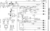
The AC power supply in my Cobra 139XLR has several zener-regulated DC taps that feed voltages to various portions of the circuit. The 100uf cap in the circuit shown below gets EXTREMELY hot. All of the components in the circuit checked good, but I replaced them with the same values only higher voltage and wattage ratings. Regulated voltage is within specified limits. This particulsr tap only supplies one point in the circuit. The base bias on the buffer for the carrier osc output. Radio works fine. but this hot cap bothers me. Any ideas to prevent it from heating up so much ??

- J.J. 399

voltage tapUntitled.png
 
  • Like
Reactions: Cable Guy

Google:
Capacitors have resistance in their electrodes and dielectrics. This resistance generates heat when AC current like ripple current passes through capacitors.

I'd guess cap is faulty, excessive noise from zener or a dirty power supply with excessive AC current.
 
Last edited:
Cap checked good, but changed it to a higher voltage rating. Checked on my scope, and power supply is clean w/o ripple. Tried it with a battery and cap still heats up. There are three other Zener regulated voltage taps, and none of the caps on them get hot.

J.J.
 
  • Wow
Reactions: Tech5
Check the wirewound 150 ohm resistor hasn't shorted to 0 ohms. A 0 ohm condition would enable excessive current to go straight to ground through the cap, which would certainly make it heat up like that !
 
  • Like
Reactions: unit_399
I've got to think about this.....

I would think that.... if the new cap is 35v .... it should be able to take the whole 13.8 vdc across it without a problem.

For the cap to heat itself up.... it seems like it would have to be drawing current.... and that would sound to me like it was leaking!!! But the new cap does it too... so unless that is an infant mortality failure.... the cap shouldn't be leaking.

Is there any chance that a nearby component is getting hot.... and causing the cap to get hot externally?

Other than that.... it may sound dumb.... but could the cap OR THE BOARD SILKSCREEN be reversed??? If the board were mismarked and the cap put in according to that..... the cap would be in reverse polarity.. and it wouldn't be good for it.

Just throwing ideas out....
 
Cap is definitely not backwards, and the board is not mismarked. The negative lead of the cap is connected to the ground trace.
BC, I hadn't thought about the 150 ohm wirewound being shorted. A carbon resistor can't short, but a wirewound sure could. I pulled a 150 ohm WW resistor out of an 858SSb parts board. Checked right on 150 ohms. I will change out the one in my base radio tomorrow. Crossing my fingers.

J.J. 399
 
Last edited:
my thought would be that there is some ripple current that is causing the cap to heat up, but you said you tried it on an external DC supply right?
if so, that would take my idea out of consideration for the most part.

you could just say F it and replace the circuit with a 7808, but of course that would mean admitting defeat!
LC
 
Cap is definitely not backwards, and the board is not mismarked. The negative lead of the cap is connected to the ground trace.
BC, I hadn't thought about the 150 ohm wirewound being shorted. A carbon resistor can't short, but a wirewound sure could. I pulled a 150 ohm WW resistor out of an 858SSb parts board. Checked right on 150 ohms. I will change out the one in my base radio tomorrow. Crossing my fingers.

J.J. 399
This is a really weird problem!

I hate to seem a "pain"... but if that 150 ohm resistor was shorted I would think that it would be the ZENER complaining.... not the capacitor. The cap is a 35 volter... and we are only talking about 13.8 vdc here. That resistor however... acts as a current limiter for the zener. Once that zener hits the knee it will try to pass whatever current it's supply will feed to it. If too much current.... "pop goes the diode!".

Another way to approach this might be..... measure that 150 ohm resistor...then put it back in the circuit, then measure the voltage across it. THAT will tell you how much current is being pulled. From there... you could pull one leg of the zener, one leg of the cap, one leg of a NUMBER of those parts.... and see which one is actually pulling the current. The current draw will go away when the "culprit" is found.

Again.... just throwing out "thoughts and ideas" as they occur!!!!!
Bob

[edited to add]
one more dumb idea just happened......
disconnect one end of the 150 ohm resistor(so that the supply is cut off) and measure the voltage on the zener/capacitor. It might sound goofy... but if something out on the board is shorted... maybe it is "back feeding" voltage from a spot and there is no current limiting (due to the short) to keep excess current from coming in and heating something up!
 
  • Like
Reactions: BC Coyote
I just snipped this out of the SAMS for the 139XLR just to help "focus ME!".

The only 7.5v zener I see is D25 (feeding CKT TRACE #6, a 7.82 volt source) but the limiting resistor is only 68 ohms. Is this the right place or is there another I am missing?

Just trying to get "better dialed in" to the patient........

[edited to add]
I just looked at the parts layout in the SAMS.....
C101 is pretty much right next door to D25(the 7.5 v zener).
Is there any chance that D25 is heating up .... and just "baking" C101 right next to it? Have you tried to isolate/touch JUST the diode under heated conditions and see if it isn't hot too? Just thinking of possibilities....
 

Attachments

  • Screenshot from 2024-08-20 10-17-36.png
    Screenshot from 2024-08-20 10-17-36.png
    278.4 KB · Views: 3
Last edited:
  • Like
Reactions: Tech5
The only 7.5v zener I see is D25 (feeding CKT TRACE #6, a 7.82 volt source) but the limiting resistor is only 68 ohms. Is this the right place or is there another I am missing?
Guitar -
That is the right place. Funny thing though, The sams for the Cobra 138 and139 xlr are the only 858SSb chassis that show a 68 ohm resistor for R113. All the other chassis I checked (Realistics, Robyn, President, Teaberry) all show a 150 ohm resistor in the R113 location. Maybe the 150 ohm was a running change Uniden made, but didn't issue a service bulletin. I'll check to see if my 139XLR has the 68 ohm. If it does I'll change it to 150. Maybe that will solve the problem. Thank you for your help. NEVER a "pain."

J.J. 399
 
  • Like
Reactions: guitar_199
I can only come up with two causes to this mysterious capacitor and that is wrong polarity, which it is not as unit_339 stated, or a bad capacitor and since you fed the regulator from a battery, or DC supply, we can leave out all the thoughts about excessive ripple. The zener diode (7V5 1W) itself does not affect the capacitor in any way unless it is located very close to it and run very hot. This zener should run cool with only (Iz ~49 mA) 370 mW pd. Also, as soon as there is even a light load on the 7,5 volts the power dissipation decreases and then it runs cooler.

Since you used the scope and found no anomalies we can be assured that the VR is feed by pure DC. If you put a resistor with higher resistance it will decrease the voltage regulators ability to meet up with an increased load, but here we are dealing with a very light load so I guess it does not matter. You bet I would like to have that Cobra on my bench, but I am in Sweden! :LOL:

Think I will continue with the Spirfire MarkII! :giggle:
 

Attachments

  • Shack.jpg
    Shack.jpg
    3.1 MB · Views: 6
Last edited:
UPDATE: Problem solved !!

I opened up my 139XLR and removed R113. When I measured its value I found it to be 68.1 ohms. I replaced it with the 150 Ohm R113 that I removed from an 858SSb parts board, and now C101 is cool as a cucumber.

Evidentally this was a running production change that Uniden made, but never issued a service bulletin because the hot cap didn't affect operation of the radio.
The 139XLR was the first 858 chassis on the market, and Sams #126 showed the original 858SSb circuit and 68 ohm R113. Subsequent Sams for later 858s all show the 150 ohm part.

Thanks to Guitar_199 for noticing the R113 discrepancy and to BC Coyote for pointing me in the right direction to begin with.
AND . . . definitely thanks to everyone else for their insight and suggestions. This was a really weird problem, but once again WWDX forum members figured it out. You guys are the best !!

- J.J. 399
 
Last edited:

dxChat
Help Users
  • No one is chatting at the moment.