You are using an out of date browser. It may not display this or other websites correctly.
You should upgrade or use an alternative browser.
You should upgrade or use an alternative browser.
-
You can now help support WorldwideDX when you shop on Amazon at no additional cost to you! Simply follow this Shop on Amazon link first and a portion of any purchase is sent to WorldwideDX to help with site costs.
-
The Retevis Holidays giveaway winner has been selected! Check Here to see who won!
Who works on Texas Star amps?
- Thread starter Lkaskel
- Start date
'that's great, is there a diagram with the parts locations?Texas Star DX 400 - DX 500CB-Tricks.com
DX 400 and DX 500 PARTS LIST
Capacitors
Value NOTES: 15pF Ceramic Disc 0.022uF to .1uF Ceramic Disc 1000pF Ceramic Disc 1000 uF 16v Electrolytic 150pF Ceramic Disc 330pF Ceramic Disc 0.068 uF TO .1uF Glass, Ceramic Disc or Monolithic 0.068 uF TO .1uF Glass, Ceramic Disc or Monolithic 120pF (DX400) Silver Mica 330pF (DX500) Silver Mica 0.068uF to .2uF Glass, Ceramic Disc or Monolithic 0.0015uF (DX400) Polypropylene 0.0012uF (DX500) Polypropylene 0.068uF to .2uF Glass, Ceramic Disc or Monolithic 330pF Silver Mica 330pF Silver Mica 0.068 uF TO .1uF Glass, Ceramic Disc or Monolithic 1200pF (DX400) Stacked Mica (SEMO) 1000pF (DX500) Stacked Mica (SEMO) 0.068 uF TO .1uF Glass, Ceramic Disc or Monolithic 0.01uF Ceramic Disc or Monolithic 0.068uF to .2uF Glass, Ceramic Disc or Monolithic 0.0015uF (DX400) Polypropylene 0.0012uF (DX500) Polypropylene 0.068uF to .2uF Glass, Ceramic Disc or Monolithic 330pF Silver Mica 330pF Silver Mica 0.068uF TO .1uF Ceramic Disc or Monolithic 1200pF (DX400) Stacked Mica (SEMO) 1000pF (DX500) Stacked Mica (SEMO) 0.068 uF TO .1uF Ceramic Disc or Monolithic 0.01uF Ceramic Disc Monolithic 0.068 uF TO .1uF Ceramic Disc Monolithic 33uF 25v Electrolytic 0.068 uF TO .1uF Glass, Ceramic Disc or Monolithic 10uF 25v Electrolytic 0.01uF Ceramic Disc Monolithic 91pF Silver Mica
Resistors
Value NOTES: 470 ohm 1/4W Carbon 10 ohm 2W (DX400) Metal Oxide 120 ohm 2W (DX400) Metal Oxide 200 ohm 2W (DX500) Metal Oxide 75 ohm 4W Metal Oxide 6 ohm 4W Metal Oxide 68K Carbon 470 Carbon 100 ohm 2W Metal Oxide 1.8 ohm 1/2W Carbon 39 ohm 3W Metal Oxide 10 ohm 1/2W Carbon 10 ohm 1/2W Carbon 39 ohm 3W Metal Oxide 25 ohm 5W Wire Wound 1.8 ohm 1/2W Carbon 39 ohm 3W Metal Oxide 10 ohm 1/2W Carbon 10 ohm 1/2W Carbon 39 ohm 3W Metal Oxide 25 ohm 5W Wire Wound 100 ohm 2W Metal Oxide 15K ohm 1/4W (DX400) Carbon 30K ohm 1/4W (DX500) Carbon 1K ohm 1/4W Carbon 27K ohm 1/4W Carbon
Diodes
Value NOTES: 1N4001 1N4148 MR750 1N4148
Toroids
Value NOTES: Toroid Combiner Bifiliar (5 Turns #22) on 30MHz Ferrite Toroid Core ½" O.D., ¼" I.D. 1/8" x 1/8" Thick. Toroid Combiner Bifiliar (5 Turns #22) on 30MHz Ferrite Toroid Core ½" O.D., ¼" I.D. 1/8" x 1/8" Thick.
Transistors
Value NOTES: 2N2907A 2N4125 2SC2290 (DX400) 2SC2879 (DX500)
Jacks
Value NOTES: SO239 RADIO SO239 ANT 1/8 Phone Key
Fuses
Value NOTES: Fuse Holder with 35A Fuse Fuse Holder with 35A Fuse
Lamps
Value NOTES: 18v 40ma Lamp #2682 14v 80ma Lamp
Value NOTES: 4 Position Switch Bank Button Bezel Lens (POWER) Lens (REC AMP) Lens (SELECT A WATT) Lens (DELAY)
Value NOTES: Stackpole 5 Turns (DX400) Stackpole 2 Turns (DX500) Stackpole 4 Turns Stackpole 5 Turns (DX400) Stackpole 2 Turns (DX500) Stackpole 4 Turns Ferrite Bead 13/64" Dia. x 7/16 long
I
I'm trying to see how to get the picture's out of my file's on my laptop.That's great, is there a diagram with the parts locations?
Hope this one work's Let me know'that's great, is there a diagram with the parts locations?
I
I'm trying to see how to get the picture's out of my file's on my laptop.
Attachments
Also you need to check the bias before you put RF into the amp or it will blow those Transistor's. 0.676 / 0.68 Bias Volt Setting would be good. I would've put HG2879's in there to replace those DEI's they would run better and also, I would replace the Output Capacitor's with 1000pf Metal Clads. Test the Input SWR normally there set pretty good already then check the Output power with the Cap that's in there. If you could remove the Caps you could use a 1000pf Silver Mica Cap to test it to see if there's difference in Output power. Eiter way that should keep the Reflect low between the Radio and Amp. I hope this will help Let me know.Hope this one work's Let me know
This is how you set the Bias Volts for these Amps.Hope this one work's Let me know
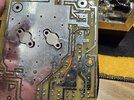
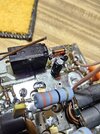
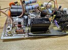
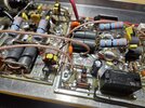
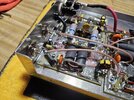
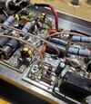
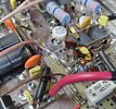
How'zit by looking at the combiner it shows signs that it got hot. If you test that 100ohm 2w metal oxide resistor it might be bad and it will blow those DEI transistors in that section. The splitter on the input should be alright. Do you have a transistor tester like those DS55 or so? I would test those transistors before putting everything back together. If it's okay what's your email so I can drop you my number.Well after a near complete disassembly, trace repair, some parts replacements and tons of cleaning this is where I'm at. Much better looking than where it started and slowly getting it back together with little times available.
Please don't be too harsh with the criticism.
View attachment 66266View attachment 66267View attachment 66268View attachment 66269View attachment 66270View attachment 66271View attachment 66272
Nothing ever got hot, it was never even powered up. There was tons of flux all over everything but after it was all cleaned up was all good. Report comic soon.How'zit by looking at the combiner it shows signs that it got hot. If you test that 100ohm 2w metal oxide resistor it might be bad and it will blow those DEI transistors in that section. The splitter on the input should be alright. Do you have a transistor tester like those DS55 or so? I would test those transistors before putting everything back together. If it's okay what's your email so I can drop you my number.
Cool brother almost there then. Just watch that video to manually key the amp and set the bias before you hookup the radio to it. Then it should be all good.Nothing ever got hot, it was never even powered up. There was tons of flux all over everything but after it was all cleaned up was all good. Report comic soon.
Gentlemen, it turned out to be a success. All assembled, checked bias impedance and voltage and checked good.
Pass through tune about 1.2:1 and with amplifier on it actually was just a tad lower at about a 1.1. With about 4 watts in I got about 100 watt carrier with little swing because the test radio swings very little and the power supply peters out. So far so good. Tomorrow I'll put it on the bigger supply with a swinging radio to see if anything gives but I don't expect it to.
I appreciate all of your help Gentlemen!
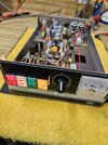
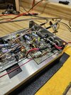
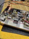
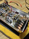
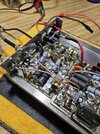


I'm looking and I can't see the catastrophe that was. You seem to have done a bang up job it looks great!
You still shouldn't have had to go though all that but you've made lemonade out of the lemon!
You still shouldn't have had to go though all that but you've made lemonade out of the lemon!
Thankfully that was the case my friend. Makes me wonder though, if I had been a regular consumer and just put power to it. 2 broken traces, the delay diode was incorrect, the electrolytic leg not even on the pad, blobs galore creating shorts...... how would that have turned out for an everyday consumer? It may have let out magic smoke, not operated at all, who knows.... and what kind of support would they have received? It really is sad!I'm looking and I can't see the catastrophe that was. You seem to have done a bang up job it looks great!
You still shouldn't have had to go though all that but you've made lemonade out of the lemon!
Thankfully, I have some abilities and the fine folks of wwdx to help a brother out!
Last edited:
Some of you were following my fun with the dx500 that in the end turned out well.
So today I received a surprise package from Texas star with a complete parts list aside from the transformers or pills. Not too shabby in the end to have replacement parts for if ever needed!

So today I received a surprise package from Texas star with a complete parts list aside from the transformers or pills. Not too shabby in the end to have replacement parts for if ever needed!
Good to see that, I am surprised to see the switch gang included.Some of you were following my fun with the dx500 that in the end turned out well.
So today I received a surprise package from Texas star with a complete parts list aside from the transformers or pills. Not too shabby in the end to have replacement parts for if ever needed!
View attachment 66490
It restores some faith that they did not leave you hanging.
Still makes you wonder about testing before they get shipped.
73
Jeff
Yeah I was surprised to see the switch bank and meter in there too. Hey, in the end I'm appreciative that they didn't leave me high and dry.Good to see that, I am surprised to see the switch gang included.
It restores some faith that they did not leave you hanging.
Still makes you wonder about testing before they get shipped.
73
Jeff
dxChat
- No one is chatting at the moment.
-
@ BJ radionut:
HEATHKIT SB220 Used [.20462] - $999.00 : R&L Electronics, Amateur radio store
R&L Electronics HEATHKIT SB220 Used [.20462] - HEATHKIT SB220 MODIFIED TO ONLY WORK ON 6 METERS TESTED, HEAVILY MODIFIEDwww2.randl.com -
-
-
@ benc48:Need help lost my channel chart . Cobra 148 GTL with a 8719 and 11,1125 crystal 26.175 to 28.045 , Need the chart I can fill in the blanks slide 2ck up and 12 kc down
-

