
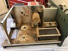
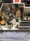
What the title says, rebuild this dinosaur Hunter Bandit 2000A or scrap it? It has 4 572 tubes of unknown condition, but I'm assuming they are air bottles. It also doesn't have the expected input band switch and tuning network. It was given to me for free. What says the hive?


You are using an out of date browser. It may not display this or other websites correctly.
You should upgrade or use an alternative browser.
You should upgrade or use an alternative browser.
-
You can now help support WorldwideDX when you shop on Amazon at no additional cost to you! Simply follow this Shop on Amazon link first and a portion of any purchase is sent to WorldwideDX to help with site costs.
Winter Project or Scrap? Bandit 2000A Amp
- Thread starter FlatlandBusa
- Start date

I would start by borrowing an amplifier that uses 572B or 811A tubes and try out this set. After a bath, of course. If they're flat, the effort to resurrect this one won't look like quite as promising a prospect. And if they deliver good power, at least there's a chance of getting wattage from your incredible hulk.
Adding a tuned input for 11 meters should be the least of your worries by the looks of it.
If the tubes check okay, my next priority would be to hipot test the high-voltage secondary of the power transformer. If you see leakage to ground from that winding, it's a doorstop.
For a really big door.
73
Adding a tuned input for 11 meters should be the least of your worries by the looks of it.
If the tubes check okay, my next priority would be to hipot test the high-voltage secondary of the power transformer. If you see leakage to ground from that winding, it's a doorstop.
For a really big door.
73
Beast of an old dinosaur.
Input tune? four 572b present a decent input impedance on all bands.
Check the grid bias resistors, 33 or 35 ohm, cant really remember.
definite replace the electrolytic caps, rectifier diodes.
If the tubes are soft, excellent candidate to drop a couple Russian triodes in.
Input tune? four 572b present a decent input impedance on all bands.
Check the grid bias resistors, 33 or 35 ohm, cant really remember.
definite replace the electrolytic caps, rectifier diodes.
If the tubes are soft, excellent candidate to drop a couple Russian triodes in.
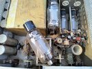
I see a blue Cetron logo on one of those tubes. They are one of the highest quality and most robust 572B tubes ever made. Do not be surprised if they are still making full output. I've got some from the 1970s that are working better than new ones today.
In a situation like this the first two things I would be getting out are the air compressor to blow the majority of the dust off of high voltage components and a variac. While you could take the time to change all of the filter caps, diodes and high pot the plate transformer, why bother?
The Transformer is either going to work or, it's not. How you test it, is not going to change the outcome and most people don't have a high pot tester. Don't get me wrong, Nomad's advice is Top Notch and professional. I'm just suggesting that I would not let the absence of having a high pot tester, prevent me from proceeding.
I've only had one situation where High pot testing saved the plate transformer that showed leakage. That was a case where the plate Transformer was stored in a cold basement and brought into a warm environment where the inside of the core started to condense and build moisture. A few hours in front of the electric heater produced a passing result that would have caused the Transformer to fail had it been plugged into the wall.
If it were me, the priority would be to obtain plate voltage and see how much current those tubes are able to draw. Also, make sure the band switch is clean before you apply RF to it. If it's been sitting as long as it looks, a little bit of dust between the two contacts can destroy the band switch. If this produces promising results, give it a complete restore from the power supply up. That's just my opinion, Others may vary.
Of course, if this was a classic Collins or something with already known substantial value, we might handle this a lot more carefully. If you don't have a variac, power it up for a quick plate voltage test, through something like a large 10 ohm wire wound resistor, in order to limit current.
The biggest, highest wattage incandescent bulb you can find makes a really good test resistor. Odds are it will have too much resistance to try operating the amplifier at all. If the bulb comes on full brightness and doesn't fade down, you have a short failure somewhere and the bulb limited the fault current to a safe value. If the bulb lights up bright and fades, have a look at the tube filaments. Might need to turn off room lights, but there should be some dim glow. If the amp has a working HV meter, you should see some movement.a quick plate voltage test, through something like a large 10 ohm wire wound resistor,
If it passes those tests, plugging it in to the outlet direct should be safe to do. And if it flunks the light-bulb test, at least you didn't introduce additional damage on top of what's causing the short. The traditional name for just plugging it in, crossing fingers and flipping the power switch is called a smoke test. And if your luck doesn't hold out using the traditional smoke test, putting the smoke back in is always more expensive than letting it out.
Just be double sure the fuse is the right size.
73
Last edited:
If you can find one today even a 100 watt light bulb has an internal resistance of over 140 ohms when lit. It's not unlikely to have 100 watts worth of bleeder resistors in the amplifier alone. It probably won't bring the voltage up high enough to spot things like a leaky filter cap or diode in the string. Although, if the bulb stays at fulbrightness, you likely have a dead short that would have popped the fuse anyway.The biggest, highest wattage incandescent bulb you can find makes a really good test resistor. Odds are it will have too much resistance to try operating the amplifier at all. If the bulb comes on full brightness and doesn't fade down, you have a short failure somewhere and the bulb limited the fault current to a safe value. If the bulb lights up bright and fades, have a look at the tube filaments. Might need to turn off room lights, but there should be some dim glow. If the amp has a working HV meter, you should see some movement.
If it passes those tests, plugging it in to the outlet direct should be safe to do. And if it flunks the light-bulb test, at least you didn't introduce additional damage on top of what's causing the short. The traditional name for just plugging it in, crossing fingers and flipping the power switch is called a smoke test. And if your luck doesn't hold out using the traditional smoke test, putting the smoke back in is always more expensive than letting it out.
Just be double sure the fuse is the right size.
73
In my mind the amplifier is already being questioned as a basket case so, I wouldn't be afraid to let the smoke out of some 50-year-old rectifiers or capacitors. That's not likely to happen through a 10 Ohm resistor either and, I just won't hang my head over the cabinet during initial power up. I'd probably pull the tubes on initial power up and check them for broken grid wires sorting to the anode, if I didn't have a tube tester. Then if a problem only happens when the tubes are installed, I know we have an internal voltage breakdown problem within one of the tubes.
Don't get me wrong, I like the light bulb test for many smaller pieces of equipment, I just find it problematic to obtain reliable results on tube amplifiers with large wattage bleeder resistors.
Based on the replies, this is worth getting to run again if the transformer is still good. I had 5 minutes to look at it earlier tonight and the fuse is blown, so that's not a good start. When I have time I'll disconnect the transformer from the rectifier and caps and see if it will make A/C voltage and light the tubes, if not its a door stop. I also found an original assembly manual (with a cigarette burn in the back few pages) and downloaded a user manual. It will be a few weeks before I can get to this since I'm currently traveling for work.
Thank you for all of the replies, I read each one in detail and learn from every one of them.
Thank you for all of the replies, I read each one in detail and learn from every one of them.
Once you get the rectifiers disconnected and the associated bleeder resistors downstream, the 100 watt light bulb test becomes very usable to test the transformer. Now it should be easy to get the filaments to light, through the resistance of the light bulb filament. Although honestly, at this point I'd just put a 4 amp fuse in it and plug it in. If the transformer is good, the tubes will light. If not the fuse will blow.Based on the replies, this is worth getting to run again if the transformer is still good. I had 5 minutes to look at it earlier tonight and the fuse is blown, so that's not a good start. When I have time I'll disconnect the transformer from the rectifier and caps and see if it will make A/C voltage and light the tubes, if not its a door stop. I also found an original assembly manual (with a cigarette burn in the back few pages) and downloaded a user manual. It will be a few weeks before I can get to this since I'm currently traveling for work.
Thank you for all of the replies, I read each one in detail and learn from every one of them.
Or two 60-Watt incandescent bulbs in parallel?100 watt light bulb
73
Those are still relatively easy to find as you probably know. Two in parallel would limit current to 1 amp. That's enough to begin seeing plate voltage, fan movement and some filament glow.Or two 60-Watt incandescent bulbs in parallel?
73
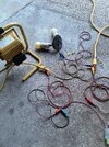
Some good news!! I had 30 minutes today to play with this. The filaments light! The meter works! It makes 2200 volts DC with only 16 volts AC ripple! The relay functions and the idle plate current come up! Both fans spin! The anode cap on one of the tubes fell off, unless that can be repaired it will need tubes. I included a picture of my redneck variac, started with a single 60 watt bulb and ended up with both 60 watt bulbs and a 500 watt work light before plugging it in direct. I had it setting in the driveway while testing it in case it let the smoke out. I'm going to set it aside until this winter, the plans are to put new HV caps in it before going further.
Attachments
Last edited:
What everyone else said.
The only 'bummer' i see about re-tubing that amp, is the same bummer I see with all the other amps with 811's, or 572's mounted horizontally;
The modern chinesium tube plates all seem to be made as thin as aluminum foil these days. Those plates melt much quicker and easier. And if horizontal, they might sag into the filament easier. But if it was me, heck yeah --- I'd go for it anyway!
She oughta clean up real nice!
My solution to the missing input network on the Gonset GSB-201 I'm restoring, was to install a cheap N7DDS ATU-100 tuner in it.... Hey, not a biggie and it werked. But you can always just slap any 100W tuner inline with it's input and do the same thing.
Last edited:
Carefully scrape the anode wire clean so solder will stick, extend it if needed to reach through the solder hole in the cap and resolder it. If you have to extend the wire, use a small enough wire so that it easily wraps around the existing one. Otherwise it may come unsoldered when resoldering the cap. Crazy glue the cap on before soldering. Be careful the existing glue in the cap does not place stress on the glass and the wire fits through it easily. If not, open the glue up with a small pick or screwdriver. That tube can be saved.Some good news!! I had 30 minutes today to play with this. The filaments light! The meter works! It makes 2200 volts DC with only 16 volts AC ripple! The relay functions and the idle plate current come up! Both fans spin! The anode cap on one of the tubes fell off, unless that can be repaired it will need tubes. I included a picture of my redneck variac, started with a single 60 watt bulb and ended up with both 60 watt bulbs and a 500 watt work light before plugging it in direct. I had it setting in the driveway while testing it in case it let the smoke out. I'm going to set it aside until this winter, the plans are to put new HV caps in it before going further.
PS: Your tubes will celebrate their half-century birthday next April! That's according to the 7513 date code I see on one. They still have an appearance that makes full output a possibility. Clear glass and bright white porcelain insulators are an indication they have not suffered from extreme electron bombardment that would have discolored them and made them darker. In the rare event they are weak, they have worked an enormous number of very easy hours.
Last edited:
What you describe is mostly seen with the 811A tube and happens even when vertically mounted. Although, to a lesser degree. Especially when used in modes with a sustained carrier. It's pretty hard for a real graphite anode on a 572B, to melt. Having said that, I've seen counterfeit 572Bs that did not have a graphite anode.What everyone else said.
The only 'bummer' i see about re-tubing that amp, is the same bummer I see with all the other amps with 811's, or 572's mounted horizontally;
The modern chinesium tube plates all seem to be made as thin as aluminum foil these days. Those plates melt much quicker and easier. And if horizontal, they might sag into the filament easier. But if it was me, heck yeah --- I'd go for it anyway!
She oughta clean up real nice!
My solution to the missing input network on the Gonset GSB-201 I'm restoring, was to install a cheap N7DDS ATU-100 tuner in it.... Hey, not a biggie and it werked. But you can always just slap any 100W tuner inline with it's input and do the same thing.
What this amplifier may have going for it, is a matched quad of Cetron 572Bs. In my opinion, this is the highest quality version of the 572B ever made. Exceptionally low failure rates and long life. Some audio guys would pay a lot to have two full output matched pairs of these tubes today.
dxChat
- No one is chatting at the moment.