• You can now help support WorldwideDX when you shop on Amazon at no additional cost to you! Simply follow this Shop on Amazon link first and a portion of any purchase is sent to WorldwideDX to help with site costs.
  • The Retevis Holidays giveaway winner has been selected! Check Here to see who won!

WM-1 meter

i'm feeling jealous mine don't have the lights but i'm very happy with the meter especially the swr section no adjustment needed
It doesn't look like a hard thing to add. A few wires and solder points on the board and I'm pretty sure nothing changed on the board. I say that because they piggy backed off of other components in the circuit.

I just had to get inside of it to see everything :ROFLMAO:
 
  • Like
Reactions: Shadetree Mechanic
A question or help from some of you wm-1 owners.

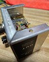
So I opened up the so-239 connector end and see this odd colored inductor inside. Almost looks like she's been a little hot before and I can't read the bands on it. Would one of you gents be kind enough to see what yours look like?

Everything seems to work fine so I wouldn't think it's shot.
Screenshot_20240403_200912_Gallery.jpgScreenshot_20240403_200917_Gallery.jpgScreenshot_20240403_200929_Gallery.jpg
Thoughts?
 
A question or help from some of you wm-1 owners.

So I opened up the so-239 connector end and see this odd colored inductor inside. Almost looks like she's been a little hot before and I can't read the bands on it. Would one of you gents be kind enough to see what yours look like?

Everything seems to work fine so I wouldn't think it's shot.
View attachment 68168View attachment 68169View attachment 68170
Thoughts?
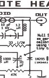
On schematic it looks like 1.2uh.
 

Attachments

  • Screenshot_20240404_055328_Samsung Notes.jpg
    Screenshot_20240404_055328_Samsung Notes.jpg
    318.9 KB · Views: 3
It doesn't look like a hard thing to add. A few wires and solder points on the board and I'm pretty sure nothing changed on the board. I say that because they piggy backed off of other components in the circuit.

I just had to get inside of it to see everything :ROFLMAO:
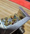
eldorado828 if you have the time can you post a picture of it for me thanks
 
  • Like
Reactions: Eldorado828
eldorado828 if you have the time can you post a picture of it for me thanks
I will when I'm back to it again. In the meantime though, this picture here shows how the wires are through the meter housing. What they did was drill two small holes and ran the wires through it and tinned the ends as seen below where the LED's are attached. The wiring behind the scenes I will have to demonstrate for you later.
DSC03928.JPG
They are fuse lamp type bulbs for the meters, at least mine were. I replaced them both as they both died. I used 2 LEDs per meter for replacements. They don't give me the full light across the meter face, but as they say, good enough for govt work.
@Smokinone
I like the way you installed the resistor between the 2 LED's, makes for a nice look and keeps the resistor floating to disperse any heat. Nice!
 
I will when I'm back to it again. In the meantime though, this picture here shows how the wires are through the meter housing. What they did was drill two small holes and ran the wires through it and tinned the ends as seen below where the LED's are attached. The wiring behind the scenes I will have to demonstrate for you later.
View attachment 68280

@Smokinone
I like the way you installed the resistor between the 2 LED's, makes for a nice look and keeps the resistor floating to disperse any heat. Nice!
thanks
 

dxChat
Help Users
  • No one is chatting at the moment.
  • @ Crawdad:
    One of the few times my tiny station gets heard on 6m!:D
  • @ Galanary:
    anyone out here familiar with the Icom IC-7300 mods
  • @ Crawdad:
    7300 very nice radio, what's to hack?
  • @ kopcicle:
    The mobile version of this site just pisses me off
  • @ unit_399:
    better to be pissed off than pissed on.
    +1