• You can now help support WorldwideDX when you shop on Amazon at no additional cost to you! Simply follow this Shop on Amazon link first and a portion of any purchase is sent to WorldwideDX to help with site costs.

cobra 25 gtl (taiwan) full restoration

gee i don't know about the counterfeit 2314's.
its been so long since i bought one i guess the supply has dried up?
LC
 
yea years back i ordered some from ebay for a rig where driver and final was blown, and they had no umpfh. ended up pulling a 1957 (which imo are good enough to leave alone) out of a parts pig rig and it worked great. i don't think HG makes drivers (but they should)
 
  • Like
Reactions: loosecannon
next few pics might be nsfw. we're gonna get real....perferted with our content........(i'll see myself out sorry)

so accomodating for the mounting bracket screw and other components. gonna build out the channel kit on this, kinda like an expo but not really, because it is diode switched with the brt-dim switch repurposed for it. the schematic im building this part from is called the expander 120 or 240 but for this is just gonna be an expander 80. because it's AM-only theres no real reason for this to go above 40. so 26.515-.955 will be the low band. i'm not gonna get TOO detailed on the channel kit install, but if you know how you know how. it involves a trace cut. Godspeed
 

Attachments

  • 25gtlchkitperfcut.jpg
    25gtlchkitperfcut.jpg
    216.5 KB · Views: 13
  • Like
Reactions: Shadetree Mechanic
if you're talking about those kits that are sold by CB City Intl i don't think that scheme works with the TC9106 PLL.

or are you talking about making your own version of the EXPO model S kit?
LC
 
He's talking about breadboarding the oscillator from the "120" or the "240" kit, making it diode switched on the crystal.
 
C25 S kit install original.jpg

Rather than cutting the trace as the original instructions said to do,

C25 S kit alternate install.jpg

Cutting traces is "hokey", and if it can be avoided, ....

I think the original idea behind the "S" kit was a bad design, the Transmit Mixer don't care what you throw at it, so long as it's close to 27 MHz, it's happy.
But on Receive, capacitively bypassing the filtering in the 1st IF, lets all kind of adjacent channel bleedover come through. The VCO frequency needs to be shifted going into the 1st RX Mixer, not the 10.240 going into the 2nd mixer.

If there was a secondary 1st IF filter in parallel with the original, might work, like for "Low band", the injection frequency would be 9.79, the 1st IF would have to be 10.245, which when mixed with 9.79 comes to 455kc which works out.
If you had a 10.245 crystal in parallel with the 10.695 filter (ceramic or crystal), would work. If not, maybe a 10.2417 crystal from a Pro510 or a 10.240 crystal from a junked radio might be close enough, it is not being used as a frequency reference, but as a filter element.

I have a 3rd idea that I came up with 5 years ago, but other (life) things got in the way. I do have an AX44 in my storage that I originally had these ideas for. Amongst other stowed away radios.
 
if you're talking about those kits that are sold by CB City Intl i don't think that scheme works with the TC9106 PLL.

or are you talking about making your own version of the EXPO model S kit?
LC
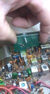
https://www.cbcintl.com/expander160.htm i have used it to switch between 10.24 and 9.79 and the oscillator is connected with a small rg174 coax so it wont leak. the internal 10.24 turns into something with a single job of establishing steps where down the line its injected in via the oscillator
 
A kit top.jpg
A kit btm.jpg

Smallest Oscillator Injector kit You will ever see, Rev 1. I goofed on the copper trace naming of the Uniden radio, should've been 76XL not 76LTD (which would be the Cobra 29LTD). But, it is diode switched, MicroMELF sized diodes. Hand soldered, not oven. I hadn't cleaned the flux off of this board, yet. Mostly 0805 SMD, other than the crystals and trimmers on the top side. I hadn't decided on the series chokes for the crystals, yet (I have), those are the unpopulated horizontal solder pads above the 222 resistors. Size of the board is about 1" wide to a hair over 1.25" long. Change the crystals, and it can work as an "S" kit.

Rev 2 fixes this board's mistakes. I have Rev 2 cued up on a board manufacturer's site, along with a few other boards I have designed for other purposes.
 
Is it permissible to change the TX 10.240 to 10.695 and inject your own ~16mhz signal?

On paper it looks as if it would be one freq for both TX and rx. Then a freq counter could be added.
 

dxChat
Help Users
  • No one is chatting at the moment.