I would like to run this by the WWRF expertise before I connect everything and break something...
Wacom WP-637 Band-Reject Duplexer
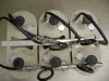
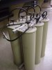
Two pics attached (before I tuned it)
One datasheet
One response curve graph
1. I thought I would measure the resistance across the center and outside of the SO-239 connector just to make sure it was zero before connecting the transmitter to the duplexer. I am surprised to find that the resistance is 0.0 ohms? Is that OK?
2. Small jumper cables in between the higher frequency absorbing cavities? See pg 6 of .pdf. I removed them because after I tuned the individual cavities at the desired 145.25MHz, reconnected short jumpers, and measured again, the frequency reject peak was somewhere else. I still have these and can put them back in, and retune at the end of that cable instead of directly at the cavity connector if they do need to be there.
3. The measured response curves are shaped differently at the top (near 0dB) than the typical response curve (see pg 2). There is an additional 12dB insertion loss (due to the shape of the lower frequency notch) that I don't want, because the transmitter is going to go there.
4. At the moment I think that the 75dB notch for the receiver will be enough to block out the 25W (40dBm) from the transmitter, so I am not going to connect the transmitter through any cavities. Instead, if all goes well and I can fix the response curve, I would like to tune the other three cavities to 144.390 (only .3MHz separation!) and try to get room for a 25W aprs transmitter too. TX @ 144.390MHz, RX @ 144.650MHz, TX @ 145.250MHz, all connected to the same antenna.
Does that all sound OK or am I crazy.
Wacom WP-637 Band-Reject Duplexer
Two pics attached (before I tuned it)
One datasheet
One response curve graph
1. I thought I would measure the resistance across the center and outside of the SO-239 connector just to make sure it was zero before connecting the transmitter to the duplexer. I am surprised to find that the resistance is 0.0 ohms? Is that OK?
2. Small jumper cables in between the higher frequency absorbing cavities? See pg 6 of .pdf. I removed them because after I tuned the individual cavities at the desired 145.25MHz, reconnected short jumpers, and measured again, the frequency reject peak was somewhere else. I still have these and can put them back in, and retune at the end of that cable instead of directly at the cavity connector if they do need to be there.
3. The measured response curves are shaped differently at the top (near 0dB) than the typical response curve (see pg 2). There is an additional 12dB insertion loss (due to the shape of the lower frequency notch) that I don't want, because the transmitter is going to go there.
4. At the moment I think that the 75dB notch for the receiver will be enough to block out the 25W (40dBm) from the transmitter, so I am not going to connect the transmitter through any cavities. Instead, if all goes well and I can fix the response curve, I would like to tune the other three cavities to 144.390 (only .3MHz separation!) and try to get room for a 25W aprs transmitter too. TX @ 144.390MHz, RX @ 144.650MHz, TX @ 145.250MHz, all connected to the same antenna.
Does that all sound OK or am I crazy.