
You are using an out of date browser. It may not display this or other websites correctly.
You should upgrade or use an alternative browser.
You should upgrade or use an alternative browser.
-
You can now help support WorldwideDX when you shop on Amazon at no additional cost to you! Simply follow this Shop on Amazon link first and a portion of any purchase is sent to WorldwideDX to help with site costs.
New thread to debate V-4000
- Thread starter nosepc
- Start date
Only in your half ass backwards misinterpretation. Why would you think your modified image would be the one when I posted exactly the image I was referring too? Now if only your pictures could give you some idea of the average field this antenna creates. You've worked very hard to take an accurate picture and use it completely out of context. Notice in your image no radiated current has reached over .5 amps per meter in field strength. That's about 20% of total current. What do you think happens to average gain when those currents all line up in phase at 2.37 amps per meter in field strength as shown in frame 21?
Last edited:
Revisiting something you (nosepc) said...
So 30 degrees was your claim... Really...


These images clearly show the peak gain is between 10 and 15 degrees above the horizon... Where is this 30 degrees peak gain you claimed?
The DB
So you say that the antenna is good "because it radiates down", but it does so minimal, most of her energy is lost in a high one above 30 °. That's wasting power
You have also not shown that this antenna radiates at your claimed angle. If the radials were in fact horizontal then yes the antenna would have a high angle of radiation. The problem is the radials are not horizontal, and aren't even close. The burden of proof on this antennas radiation pattern is on your hands. Why do you not try and prove your words? The answer to that is simple, you cannot.
So 30 degrees was your claim... Really...
These images clearly show the peak gain is between 10 and 15 degrees above the horizon... Where is this 30 degrees peak gain you claimed?
The DB
I also believe the up raised radial cone does manifest a collinear aspect that Cebik described to Bob, but the result is far less that you suggest and I attribute that to cancellation of out of phase currents in the cone area. It is like pushing the feed point 8'-9' feet higher than a typical vertical 1/2 wave.
Hopefully, we'll soon know for sure.
I think there is something, far more than you seem to grasp, about the effects that completely removing the inverse currents on the bottom of the 3/4 or longer antenna can have upon the signal to horizon. There needs not to be any, although there is some, additional signal generated by the containment of the inverse currents to have a positive signal to horizon effect. Adding even a slight amount of signal in the same phase as the upper radiator can have dramatic effect on the over all strength, or gain, of the signal. I use the concept of a tail wind vs head wind to illustrate the idea for you.
Explain how a tailwind helps an airplane fly faster?
I’ve been curious about this for a long time and still have not received an explanation I can comprehend. A commercial pilot recently explained to me that a tailwind helps the commercial aircraft fly faster. However, the more I think about this, the less sense it makes.
I can see how this would be true if the plane is flying slower than the wind is blowing. But a jet liner travels at 500-600 mph at cruising altitude, so even if the wind were at the jet’s tail, it can’t possibly be blowing at or greater than the speed of the jet…can it? This would mean that the jet will be “outrunning” the wind, thereby not benefiting from it. Conversely, if the wind were a headwind, you would expect the drag on the jet to increase and the speed to slow somewhat.
Can someone explain this phenomenon in terms that make sense to this non-scientist? Thank you!
it isnt out-running the wind. think of it a different way.
imagine a ship moving through the water at 100 kph. if it's moving with the current thats going lets say 10 kph in the direction the ship is travelling, its like the whole ocean is moving 10 kph and the ship is going in the same direction. if it was moving against the current, it would have 10 kph of drag on it.
think of it another way, like trying to run down an escalator thats already moving down.
even if youre running faster than the escalator is moving, youve still got the extra speed of the escalator moving, because youre being carried on it.
the plane is being carried in the air, so if the air is moving fast, its just adding to the plane's speed. youre not just moving THROUGH the air, youre sort of moving on the air. when youre going fast especially. the tail wind can reduce drag you would have normally felt if there was no tail wind as well. like lets say youre going at 500 kph, with a 50 kpoh tailwind, its sorta like now youve only got 450 kph worth of drag on your asss. hope that made some sense
Quite simply put, it is the removing of the inverse, or out-of-phase current in the bottom of the antenna which lowers the signal to horizon angle, and the addition of the measurable in phase current no matter how slight that assists in improving the signal strength against the horizon as well. I see this in much the same way as the tail wind (or with-the-current for the ship's travel) has upon the passage of the plane - it assists for forward progress by reducing resistance to the motion of the bodies.
We know it is the lower inverse currents on longer than half wave vertical antennas that limit the lowering of the signal toward the horizon. Remove this with the antenna at any height and this angle is improved. The extra length of the antenna provides more gain, as we know. If my V4k antenna works better at 37' tip height than my 1/2 wave or 5/8 wave (which it does), then I attribute this to the antenna design, not height over objects or raised current maximum due to length. This is also a piece of your argument that is not being factored into the discussion you present.
Too simple to miss, too important to ignore.
Respectfully,
Homer
Last edited:
HomerBB,that last paragraph explains how the Vector works pretty much in a nutshell. My question just incase I missed something is what is the technical term for this process?
By the way,one time I drove my vehicle with a really good tailwind from a hurricane. My 152 hp v-6 felt like it had a 454 under the hood.
Another time I was riding 65mph on a 500 cc motorcycle. It only had enough power to run 89 mph. A passing semi rig passed me. When the rear of the rig was clearing me,I got caught up in the low area of air pressure at the rear of the rig. My bike instantly accelerated to match the semi's speed(twenty mph difference)and I pulled ahead of my brother who was riding on his 1100 cc bike. Talk about getting a boost !
I think there is something, far more than you seem to grasp, about the effects that completely removing the inverse currents on the bottom of the 3/4 or longer antenna can have upon the signal to horizon. There needs not to be any, although there is some, additional signal generated by the containment of the inverse currents to have a positive signal to horizon effect. Adding even a slight amount of signal in the same phase as the upper radiator can have dramatic effect on the over all strength, or gain, of the signal. I use the concept of a tail wind vs head wind to illustrate the idea for you.
Quite simply put, it is the removing of the inverse, or out-of-phase current in the bottom of the antenna which lowers the signal to horizon angle, and the addition of the measurable in phase current no matter how slight that assists in improving the signal strength against the horizon as well. I see this in much the same way as the tail wind (or with-the-current for the ship's travel) has upon the passage of the plane - it assists for forward progress by reducing resistance to the motion of the bodies.
We know it is the lower inverse currents on longer than half wave vertical antennas that limit the lowering of the signal toward the horizon. Remove this with the antenna at any height and this angle is improved. The extra length of the antenna provides more gain, as we know. If my V4k antenna works better at 37' tip height than my 1/2 wave or 5/8 wave (which it does), then I attribute this to the antenna design, not height over objects or raised current maximum due to length. This is also a piece of your argument that is not being factored into the discussion you present.
Too simple to miss, too important to ignore.
Respectfully,
Homer
tailwind? Perhaps it is better to put the antenna on a hill slope to Reinforce the power to exploit the radio frequency falls by its own weight... and with the full moon behind...

These forces such as terrestrial and lunar gravity also help the antenna. It can be proven scientifically
Attachments

Last edited:
(Just having fun on that last post)
At least Homer built one.....are you going to build one Nosepc?
You will never know if you do not try and we can all type until the end of time debating this subject.
Our friend Homer has built many antennas and compared them to each other and the V-4000.
73
Jeff
tailwind? Perhaps it is better to put the antenna on a hill slope to Reinforce the power to exploit the radio frequency falls by its own weight... and with the full moon behind...
At least Homer built one.....are you going to build one Nosepc?
You will never know if you do not try and we can all type until the end of time debating this subject.
Our friend Homer has built many antennas and compared them to each other and the V-4000.
73
Jeff
(Just having fun on that last post)
At least Homer built one.....are you going to build one Nosepc?
You will never know if you do not try and we can all type until the end of time debating this subject.
Our friend Homer has built many antennas and compared them to each other and the V-4000.
73
Jeff
I agree Jeff. Homer was just using a tailwind example (probably not the best idea but I see his point) to try and explain something and it appears that due to the language issue nosepc thought he was saying that the wind affects the signal radiation. That is what I see anyway.
Knowing that nothing NoSee has said makes a bit of sense, I pay little attention to his pictures. I do wonder if anyone has any idea what the heck this ball he hangs under his antennas attached by 7 strings has to do with anything? Looks like none of the models I've seen and appears to add no valuable information to the debate. Sort of what we've grown to expect from him now.
Last edited:
I myself would have to gain more knowledge on antennas in general to be able to understand what is going on with the Vector.
http://www.worldwidedx.com/attachme...vector-40000-thread-eham-collinear-vector.pdf
http://www.worldwidedx.com/attachme...vector-40000-thread-eham-collinear-vector.pdf
I myself would have to gain more knowledge on antennas in general to be able to understand what is going on with the Vector.
http://www.worldwidedx.com/attachme...vector-40000-thread-eham-collinear-vector.pdf
It would appear Marconi built this model linked above that shows perfect in phase currents with good gain in a collinear using a 180 degree phase shift. Now if ANYONE can build a working antenna based off this model, they could prove EVERYTHING I've said about how it works, was wrong. When they find the phase shift between sections that will work to drive the upper 1/2 wave is 90 degrees, they will prove the same thing I've done at least a dozen times now. The stock antenna is a 3/4 wave radiator with 90 degrees of phase correction taking place at the base.
Last edited:
It would appear Marconi built this model linked above that shows perfect in phase currents with good gain in a collinear using a 180 degree phase shift. Now if ANYONE can build a working antenna based off this model, they could prove EVERYTHING I've said about how it works, was wrong. When they find the phase shift between sections that will work to drive the upper 1/2 wave is 90 degrees, they will prove the same thing I've done at least a dozen times now. The stock antenna is a 3/4 wave radiator with 90 degrees of phase correction taking place at the base.
Oops. I tried to find one that supported your analysis.
I did some playing around with the Vector in 4NEC2. I haven't done the collinear design that was referenced in the previous two posts yet. I did learn something about how NEC, or at least 4NEC2, works...
Goal 1: To see if I can get NEC to properly show phasing data for the Vector antenna.
Goal 2: To see if I can get NEC's gain figures for the Vector design to be more in line with real world measurements.
Every model below is 1/2 wavelength above real/average ground with the exception of the dipole reference. For each model I have a picture that shows both phase and the vertical radiation pattern. Also included for each model is the NEC file I used in case anyone wishes to experiment themselves, or find faults with my methods or findings.
First the dipole reference. It has been mounted at the same tip height as the other models instead of the same base or feedpoint height. This adjustment was necessary for an accurate measure of unity gain for a dipole (dBd reference).


Next I show the base vector model. This is the very same model that was used in my last post in this thread.


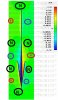
As we can see, the bottom 1/4 wavelength of the 3/4 wavelength radiator and the radials that make up the "basket" area are in phase with each other and out of phase with the upper 1/2 wavelength of the 3/4 wavelength radiator.
In the next model there is one and only one difference from the model above, I moved the feedpoint up to a higher location. Instead of being at segment 1 it is now in segment 55 of 150 total segments.


As we can see that according to 4NEC2 the entire antenna is now in phase, and we see a higher gain as a result. Perhaps this can be part of a work-around to get more accurate results using NEC based programs and the vector design, but I am not satisfied as to the accuracy of this model. My current thought on this change is it needs more study.
In the model below I reset the feedpoint back to the original location and made another change to the model...


What I did was change the orientation of the wires used for the radials. They are in the exact same physical location but the change allows me to control how 4NEC2 calculates their phasing. Using this method I have found that I can change the phase of any wire on any antenna in 4NEC2 to have whichever phase I want it to have.
This produced the correct phasing as demonstrated by the CST based time domain model that is available on these forums. Unfortunately when looking at the "Vertical plane" gain plot it looks exactly like the plot from the first Vector model above.
This suggests that the phase data has nothing to do with the gain data in NEC, or at least 4NEC2. I believe that this simply shows a limitation of this modeling program as in the real world the radial elements being in or out of phase with the upper radial section would make a huge difference to the radiation pattern from the antenna...
---
I seem to have achieved both goals that I initially set out to achieve, however Goal 1 was not achieved to my satisfaction, and Goal 2 was only apparently achieved as the visual change in phase does not change how 4NEC2 actually handles the radiation pattern or gain of the antenna.
I have shown that phasing data as shown by NEC, or at the very least 4NEC2, can be manipulated to show pretty much anything I wish, thus any model in the future that shows phasing in any NEC based program will be questioned and/or examined.
The DB
Goal 1: To see if I can get NEC to properly show phasing data for the Vector antenna.
Goal 2: To see if I can get NEC's gain figures for the Vector design to be more in line with real world measurements.
Every model below is 1/2 wavelength above real/average ground with the exception of the dipole reference. For each model I have a picture that shows both phase and the vertical radiation pattern. Also included for each model is the NEC file I used in case anyone wishes to experiment themselves, or find faults with my methods or findings.
First the dipole reference. It has been mounted at the same tip height as the other models instead of the same base or feedpoint height. This adjustment was necessary for an accurate measure of unity gain for a dipole (dBd reference).
Code:
CE
GW	1	50	0	0	8.25	0	0	13.75	.0001
GE	-1
GN	2	0	0	0	4	0.003
EK
EX	0	1	25	0	1	0	0	'Voltage source
FR	0	0	0	0	27.185	0
EN
Next I show the base vector model. This is the very same model that was used in my last post in this thread.
Code:
CE
GW	1	150	0	0	5.5	0	0	13.75	.0001
GW	3	50	.87	0	8.109	0	0	5.5	.0001
GW	4	50	-.87	0	8.109	0	0	5.5	.0001
GW	5	50	0	-.87	8.109	0	0	5.5	.0001
GW	6	50	0	.87	8.109	0	0	5.5	.0001
GE	-1
GN	2	0	0	0	4	0.003
EK
EX	0	1	1	0	1	0	0	'Voltage source
FR	0	0	0	0	27.185	0
EN
As we can see, the bottom 1/4 wavelength of the 3/4 wavelength radiator and the radials that make up the "basket" area are in phase with each other and out of phase with the upper 1/2 wavelength of the 3/4 wavelength radiator.
In the next model there is one and only one difference from the model above, I moved the feedpoint up to a higher location. Instead of being at segment 1 it is now in segment 55 of 150 total segments.
Code:
CE
GW	1	150	0	0	5.5	0	0	13.75	.0001
GW	3	50	.87	0	8.109	0	0	5.5	.0001
GW	4	50	-.87	0	8.109	0	0	5.5	.0001
GW	5	50	0	-.87	8.109	0	0	5.5	.0001
GW	6	50	0	.87	8.109	0	0	5.5	.0001
GE	-1
GN	2	0	0	0	4	0.003
EK
EX	0	1	55	0	1	0	0	'Voltage source
FR	0	0	0	0	27.185	0
EN
As we can see that according to 4NEC2 the entire antenna is now in phase, and we see a higher gain as a result. Perhaps this can be part of a work-around to get more accurate results using NEC based programs and the vector design, but I am not satisfied as to the accuracy of this model. My current thought on this change is it needs more study.
In the model below I reset the feedpoint back to the original location and made another change to the model...
Code:
CE
GW	1	150	0	0	5.5	0	0	13.75	.0001
GW	3	50	0	0	5.5	.87	0	8.109	.0001
GW	4	50	0	0	5.5	-.87	0	8.109	.0001
GW	5	50	0	0	5.5	0	-.87	8.109	.0001
GW	6	50	0	0	5.5	0	.87	8.109	.0001
GE	-1
GN	2	0	0	0	4	0.003
EK
EX	0	1	1	0	1	0	0	'Voltage source
FR	0	0	0	0	27.185	0
EN
What I did was change the orientation of the wires used for the radials. They are in the exact same physical location but the change allows me to control how 4NEC2 calculates their phasing. Using this method I have found that I can change the phase of any wire on any antenna in 4NEC2 to have whichever phase I want it to have.
This produced the correct phasing as demonstrated by the CST based time domain model that is available on these forums. Unfortunately when looking at the "Vertical plane" gain plot it looks exactly like the plot from the first Vector model above.
This suggests that the phase data has nothing to do with the gain data in NEC, or at least 4NEC2. I believe that this simply shows a limitation of this modeling program as in the real world the radial elements being in or out of phase with the upper radial section would make a huge difference to the radiation pattern from the antenna...
---
I seem to have achieved both goals that I initially set out to achieve, however Goal 1 was not achieved to my satisfaction, and Goal 2 was only apparently achieved as the visual change in phase does not change how 4NEC2 actually handles the radiation pattern or gain of the antenna.
I have shown that phasing data as shown by NEC, or at the very least 4NEC2, can be manipulated to show pretty much anything I wish, thus any model in the future that shows phasing in any NEC based program will be questioned and/or examined.
The DB
Last edited:

dxChat
- No one is chatting at the moment.
-
-
-
@ BJ radionut:
Discord - A New Way to Chat with Friends & Communities
Discord is the easiest way to communicate over voice, video, and text. Chat, hang out, and stay close with your friends and communities.discord.com
-
-
