• You can now help support WorldwideDX when you shop on Amazon at no additional cost to you! Simply follow this Shop on Amazon link first and a portion of any purchase is sent to WorldwideDX to help with site costs.

New thread to debate V-4000

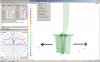
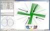
The way I manually made the radials to show the radials as being in phase with the upper 1/2 wavelength of the vertical 3/4 wavelength element is as is shown below... Namely the XYZ1 is at the base of the 3/4 wavelength vertical element and XYZ2 are the tips of the various radials.

I see, you manually made the radials and they show in phase, not you manually made the radials show in phase.


Code:
CM 11 meter cb by ghz24
CE
SY z=324	'driven element length
SY rh=108	'ring height
SY zp=30	'avoid segment errors durring sweeps
SY rsf=0.5	'changes ring diameter
SY agl=240
SY rrf=-0.1
SY ssf=-0.1
GW	1	13	0	0	0+agl	0	0	zp+agl	0.35
GW	2	101	0	0	zp+agl	0	0	z+agl	0.35260011
GW	6	49	0	2	0+agl	0	30*rsf	rh+agl	0.35260011
GW	7	49	0	-2	0+agl	0	-30*rsf	rh+agl	0.35260011
GW	8	49	-2	0	0+agl	-30*rsf	0	rh+agl	0.35260011
GW	9	49	2	0	0+agl	30*rsf	0	rh+agl	0.35260011
GW	16	1	0	0	0+agl	0	2	0+agl	0.35260011+ssf
GW	17	1	0	0	0+agl	0	-2	0+agl	0.35260011+ssf
GW	18	1	0	0	0+agl	-2	0	0+agl	0.35260011+ssf
GW	19	1	0	0	0+agl	2	0	0+agl	0.35260011+ssf
GW	100	3	29.99994*rsf	0*rsf	0+rh+agl	27.7163225*rsf	11.4804889*rsf	0+rh+agl	0.35260011+rrf
GW	101	3	27.7163225*rsf	11.4804889*rsf	0+rh+agl	21.2131466*rsf	21.2131466*rsf	0+rh+agl	0.35260011+rrf
GW	102	3	21.2131466*rsf	21.2131466*rsf	0+rh+agl	11.4804889*rsf	27.7163225*rsf	0+rh+agl	0.35260011+rrf
GW	103	3	11.4804889*rsf	27.7163225*rsf	0+rh+agl	0*rsf	29.99994*rsf	0+rh+agl	0.35260011+rrf
GW	104	3	0*rsf	29.99994*rsf	0+rh+agl	-11.480489*rsf	27.7163225*rsf	0+rh+agl	0.35260011+rrf
GW	105	3	-11.480489*rsf	27.7163225*rsf	0+rh+agl	-21.213147*rsf	21.2131466*rsf	0+rh+agl	0.35260011+rrf
GW	106	3	-21.213147*rsf	21.2131466*rsf	0+rh+agl	-27.716323*rsf	11.4804889*rsf	0+rh+agl	0.35260011+rrf
GW	107	3	-27.716323*rsf	11.4804889*rsf	0+rh+agl	-29.99994*rsf	0*rsf	0+rh+agl	0.35260011+rrf
GW	108	3	-29.99994*rsf	0*rsf	0+rh+agl	-27.716323*rsf	-11.480489*rsf	0+rh+agl	0.35260011+rrf
GW	109	3	-27.716323*rsf	-11.480489*rsf	0+rh+agl	-21.213147*rsf	-21.213147*rsf	0+rh+agl	0.35260011+rrf
GW	110	3	-21.213147*rsf	-21.213147*rsf	0+rh+agl	-11.480489*rsf	-27.716323*rsf	0+rh+agl	0.35260011+rrf
GW	111	3	-11.480489*rsf	-27.716323*rsf	0+rh+agl	0*rsf	-29.99994*rsf	0+rh+agl	0.35260011+rrf
GW	112	3	0*rsf	-29.99994*rsf	0+rh+agl	11.4804889*rsf	-27.716323*rsf	0+rh+agl	0.35260011+rrf
GW	113	3	11.4804889*rsf	-27.716323*rsf	0+rh+agl	21.2131466*rsf	-21.213147*rsf	0+rh+agl	0.35260011+rrf
GW	114	3	21.2131466*rsf	-21.213147*rsf	0+rh+agl	27.7163225*rsf	-11.480489*rsf	0+rh+agl	0.35260011+rrf
GW	115	3	27.7163225*rsf	-11.480489*rsf	0+rh+agl	29.99994*rsf	0*rsf	0+rh+agl	0.35260011+rrf
GS	0	0	0.0254
GE	0
GN	-1
EK
EX	0	1	7	0	6.12e-17	1	0
FR	0	0	0	0	27.18	0
EN
not the highest gain version I have but it's more like the actual measurements.
Has a slight up-tilt.
 
ghz24, Homer and Booty Monster have built the S4/V4 styled antenna, and I think both found out the real antenna does not work right when they tried to attach the radial bottoms directly to the bottom of the radiator using a compression strap of some sort. If I'm wrong they can explain better, but IMO they both got too close in the beginning.

IMO, this is a real world issue as well as a modeling issue, and this is why I build a small hub for when I have wires that will attach at sharp angles.

I could be wrong, but I don't think the small hub designs are just a matter of convenience in kit design for such antennas as the Starduster, A99 with GPK hub, the S4, and the Vector.

When I've posted examples of these antennas as Eznec model results I've shown blow up examples of this hub so the guys can see it. I've also talked about the issue with both Homer and BM, when they had problems with their original designs that had issues. To me setting the radials flush against the radials, even if the tubing is made flat is not a good idea. It looks to make the resistive part of the antenna get too close to zero and adding inductance to the top of the radiator will not fix that problem. A few have said I was just trying too hard to get the model looking just like the real thing.

I also model the Skeleton Sleeve Fed Monopole (SSFM) the other day with a very wide radial offset at the base, and the radials set virtually parallel. I got a very good match with the author's design at 2 meters and 11 meters, but the antenna had very little gain as I recall. I did different iterations in the process of bringing the radial elements closer and closer to the bottom element, and the performance improved while the match got lower and lower. This model, as designed, is fed at bottom of the radiator. As a result I found about .75" spacing between the radials and the radiator is minimum spacing, and about the best performance with maybe 1" showing a little better match without the gain starting to fade. I think I saw the resistive going down and the (-) reactance going up, thus the antenna match point needed to be higher up the radiator, and the radiator needed to be longer to remain resonant.

I told Bob the other day that I found the wide spacing J-pole was no-way-no too, and for the same reasons. IMO this also makes the J-pole show much less balance at the feed point and more CMC issues and skewing of the pattern is likely to occur.

I don't think 4nec2 works much different than my Eznec in this respect, and I figure the lack of a hub in most of these models made without a small hub that offsets the radials from the radiator will likely result in poor models.

So you need those little wires ghz24.

BTW, am I right you have the radiator set at about 32' feet long and the radials set at 107" in your model? I'm trying to see if I got my math right.
 
Last edited:
  • Like
Reactions: 1 person
I see, you manually made the radials and they show in phase, not you manually made the radials show in phase.

not the highest gain version I have but it's more like the actual measurements.
Has a slight up-tilt.

ghz24, what do see when you post: "Has a slight up-tilt?"
 
Sigma 4 gain in cone.

GAIN ON STAGE IRRADIATION IS CONE IS A FANTASY.

Many years ago a radiotecnician colleague told me "had invented putting gain directional antennas to the 4 cardinal points."

I said that the gain was apparent, since if an antenna radiating in the sense that he would say, does the opposite in the opposite direction, opposing its phase and the gain was zero.

Here it is the same, only I'm the "only dumb" I notice thereof

;)

nosepc

(If they consider it very necessary, I can go and get photographs of the towers and antennas.)
 

Attachments

  • fase-cono.jpg
    fase-cono.jpg
    364.4 KB · Views: 2
Last edited:
@ ghz 24..

Good model ! well done, u could be Arie him self :)

i dont know if u use a nec4 engine...

if not (using: nec4mp) : 2,41dBI ...roughly at a 5 degree upward peak
(agt = 0,991. resonant 27.415 27,15 ohms).

@ Marconi..so..a freespace elevation pattern like a flat figure 8 ..but the pattern has a slight upwards effect...like a push up bra :)


regards,
H.
 
ghz24, Homer and Booty Monster have built the S4/V4 styled antenna, and I think both found out the real antenna does not work right when they tried to attach the radial bottoms directly to the bottom of the radiator using a compression strap of some sort. If I'm wrong they can explain better, but IMO they both got too close in the beginning.

IMO, this is a real world issue as well as a modeling issue, and this is why I build a small hub for when I have wires that will attach at sharp angles.

I could be wrong, but I don't think the small hub designs are just a matter of convenience in kit design for such antennas as the Starduster, A99 with GPK hub, the S4, and the Vector.

When I've posted examples of these antennas as Eznec model results I've shown blow up examples of this hub so the guys can see it. I've also talked about the issue with both Homer and BM, when they had problems with their original designs that had issues. To me setting the radials flush against the radials, even if the tubing is made flat is not a good idea. It looks to make the resistive part of the antenna get too close to zero and adding inductance to the top of the radiator will not fix that problem. A few have said I was just trying too hard to get the model looking just like the real thing.

I also model the Skeleton Sleeve Fed Monopole (SSFM) the other day with a very wide radial offset at the base, and the radials set virtually parallel. I got a very good match with the author's design at 2 meters and 11 meters, but the antenna had very little gain as I recall. I did different iterations in the process of bringing the radial elements closer and closer to the bottom element, and the performance improved while the match got lower and lower. This model, as designed, is fed at bottom of the radiator. As a result I found about .75" spacing between the radials and the radiator is minimum spacing, and about the best performance with maybe 1" showing a little better match without the gain starting to fade. I think I saw the resistive going down and the (-) reactance going up, thus the antenna match point needed to be higher up the radiator, and the radiator needed to be longer to remain resonant.

I told Bob the other day that I found the wide spacing J-pole was no-way-no too, and for the same reasons. IMO this also makes the J-pole show much less balance at the feed point and more CMC issues and skewing of the pattern is likely to occur.

I don't think 4nec2 works much different than my Eznec in this respect, and I figure the lack of a hub in most of these models made without a small hub that offsets the radials from the radiator will likely result in poor models.

So you need those little wires ghz24.

BTW, am I right you have the radiator set at about 32' feet long and the radials set at 107" in your model? I'm trying to see if I got my math right.

Having built 173 of these antennas by hand in copper before reaching an agreement with Sirio to mass produce them, I can tell you without a doubt that the hub at the base is simply for easy bolting of the radials. Notice these radials are formed around the vertical and mounted directly to it.

This variable of adding the hub was fully field tested. The results found that the more the radials are moved away from the base (and parallel to it), the more the impedance will shift and the more the gain will drop even after adjustment of the match. Adding the hub does create a small change in impedance but nothing that can be noticed in the gain. Go beyond this point and things change for the worse.
 

Attachments

  • Connector solder.jpg
    Connector solder.jpg
    151.6 KB · Views: 3
  • Like
Reactions: 1 person
Well, Marconi, perhaps we were both wrong, but I must remain on the side of saying the antenna became easier to match, and with better readings for resonance on the MFJ-259b when I made the hub. I do not know whether it lost gain by standing the bottoms of the radials away from the vertical .75". It works awfully well, though.
 
Out of curiousity Shockwave; what does the ring at the top of the radials provide?
Capacitance?

The ring at the top of the cone does 3 minor things and can be removed in theory by lengthening the cone to compensate for resonance. Obviously the ring increases the mechanical strength of the design. The Avanti patent confirms the ring also widens the bandwidth of the tuned cone. Field tests have shown without the cone, some directional effects can be detected that favor the directions radials are in. The removed this effect.

The reason I say the ring can only be removed in theory is because you will have to lengthen the radials slightly to compensate for this. Then they will begin to confine more radiation length on the vertical. The cone needs to be a resonant 1/4 wave and it needs to confine the first 1/4 wave of radiation on the vertical. Consider the velocity factor between the two and you have a narrow window where these lengths all line up to produce maximum gain on the horizon.
 
Well, Marconi, perhaps we were both wrong, but I must remain on the side of saying the antenna became easier to match, and with better readings for resonance on the MFJ-259b when I made the hub. I do not know whether it lost gain by standing the bottoms of the radials away from the vertical .75". It works awfully well, though.

Since changing the spacing at the bottom of the cone changes impedance, it will depend on the range your gamma match has to determine if finding a match will be easier or not as a result. I actually had to modify the gamma match slightly when the hub was introduced to perfect the new match.
 
I don't yet buy that nec is unable to model this antenna.

No offense intended but I am but I'm skeptical of models I can't run and see for my self.
And I can't justify the cost of CST so...

If anyone still has confidence that EZNEC (or any program besides CST) can accurately model this design, I invite them to modify the model adding the four wires # 51, 52, 53 and 54 to test if the program is calculating the in phase cone currents as shown here: THE LINK WAS NOT WORKING SO IT'S BEEN PUT IN POST # 224 BELOW.

If your model is showing a good improvement in gain like this one, I assure you it has ignored constructive radiation from the cone and functions like a 1/2 wave end fed in the model. On the other hand, if your model only peaks gain when wires 51 and 52 are approximately half the length shown here, you just built the first accurate model in another program!
 
Last edited:
SIGMA 4 CONE IRRADIATION

BECAUSE GAIN IN CONE IS A FANTASY.

Many years ago a radiotecnician colleague told me "had invented putting gain directional antennas to the 4 cardinal points."

I said that the gain was apparent, since if an antenna radiating in the sense that he would say, does the opposite in the opposite direction, opposing its phase and the gain was zero.

It can be seen in azimut at a glance that all radiation cone is automatically canceled by the opposite side that radiates in opposite phase

Here it is the same, only I'm the "only dumb" I notice thereof

;)

nosepc
 

Attachments

  • fase-cono.jpg
    fase-cono.jpg
    364.4 KB · Views: 2
  • SIGMA 4 NEC2 CONE IRADIATION.jpg
    SIGMA 4 NEC2 CONE IRADIATION.jpg
    473.3 KB · Views: 1
The link I've been referring to has not been working so I've saved it myself for linking here.
 

Attachments

  • Collinear Vector[1].pdf
    535.3 KB · Views: 20
BECAUSE GAIN IN CONE IS A FANTASY.

Many years ago a radiotecnician colleague told me "had invented putting gain directional antennas to the 4 cardinal points."

I said that the gain was apparent, since if an antenna radiating in the sense that he would say, does the opposite in the opposite direction, opposing its phase and the gain was zero.

It can be seen in azimut at a glance that all radiation cone is automatically canceled by the opposite side that radiates in opposite phase

Here it is the same, only I'm the "only dumb" I notice thereof

;)

nosepc
Just remember, you're getting what you paid for building this antenna in that software. About 10% of the total picture and understanding of the design. Using that you make a feeble attempt to unteach the other 90% of how it works in the field as tested by people even more skeptical than yourself.

Tell your BS to Clear Channel or CBC Canada. I'm sure they will be interested to know their engineers were completely incompetent (according to you) when measuring the field strength of their licensed broadcast stations.
 

dxChat
Help Users
  • No one is chatting at the moment.